Hello everyone, I’m Victor and you probably haven’t heard of me yet but I’ve got the awesome opportunity to spend some weeks during this summer working at Bitcraze. Working… Well, I’ve spent the majority of my time here getting invaluable experience, programming, flying with drones, eating incredible falafel and having fun so it’s really been a pleasure.
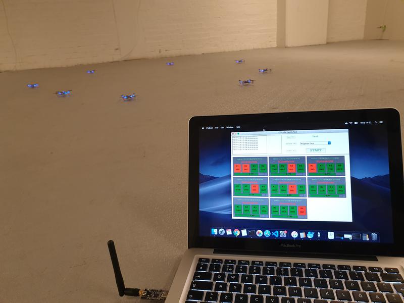
I’m quite new to both programming and electronics, so while I haven’t created any huge masterpieces of code yet, I did make a small program with a GUI that let you test the health of motors and propellers of the Crazyflie. You can run multiple ones simultaneously (I’ve tried up to 8, which works fine, even with a single radio, and you should be able to run many more) and it relies on using either Lighthouse or a Flow deck for positioning. The propeller-test is essentially the same test as the one integrated with the cfclient, however the motor-test checks the thrust-levels of the motors (by hovering in the air for x seconds) to see if any of them are off and ranks them as good/bad. The default threshold is 15% but can be changed according to needs. The program is written in Python and uses tkinter to run the GUI application and the cflib to communicate with the Crazyflie. The script can be found here.
In the end of August I’m going to study Computer Science and Engineering which I’m extremely thrilled about and this has really been a perfect preparation for that! In the future I hope to contribute to the Crazyflie projects and learn more from the great team here at Bitcraze.
We have briefly mentioned the Active marker deck earlier in our blog and in this post we will describe how it works and what it is all about.
The Active marker deck is a result of our collaboration with Qualisys, a Swedish manufacturer of high end optical tracking systems. Optical tracking systems are often referred to as motion capture (mocap) systems and are using cameras to track markers on an object. By using multiple cameras it is possible to calculate the 3D position of the markers and the object they are attached to with very high precision and accuracy. It is common to use mocap systems in robotic labs to track the position and orientation of robots, for instance quadrotors.
Passive markers
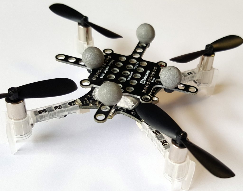
The most common marker type is the passive marker, that is reflective spheres that are attached to the robot. By using infrared flashes on the cameras, the visibility of the markers is maximized and it makes it easier for the system to detect and track them. We are selling the Motion capture marker deck to make it easy to attach markers to a Crazyflie.
To get the full pose (position, roll, pitch, yaw) of a robot, the markers must be placed in a configuration that makes it possible for the mocap system to identify the orientation. This means that there must be some asymmetry in the marker positions to understand what is front, back, up, down and so on.
With a swarm of Crazyflies, unique marker configurations makes it possible to distinguish one individual from another and track all drones simultaneously. With a larger number of robots it becomes cumbersome though to place markers in unique configurations, and one approach to solving this problem is to have known start positions for all individuals and keep track of their motions over time instead. This solution is used in the Crazyswarm for instance and all Crazyflies can use the same marker configuration in this setup. Another approach is to make it possible to distinguish one marker from another, enter the Active marker deck.
Active markers
It is possible to use infrared LEDs instead of the passive markers, this is called active markers. The LEDs are triggered by the flash from the cameras and they are easily detected as strong points of light. Since they are emitting light they can be detected further away from the camera than a passive marker and the smaller physical size also keeps them more separated when they are far away and only a few pixels are available to detect them in the camera.
Furthermore Qualisys has a technology that makes it possible to assign an id to each marker and that enables the tracking system to identify individual markers and thus uniquely identify individuals in a swarm. With different IDs on the markers, there is no need have asymmetrical configurations and the marker layout can be the same on all drones. It also reduces the risk of errors in the estimated pose, since there is more information available.
The deck
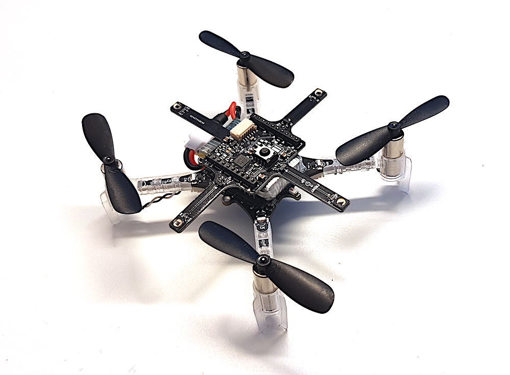
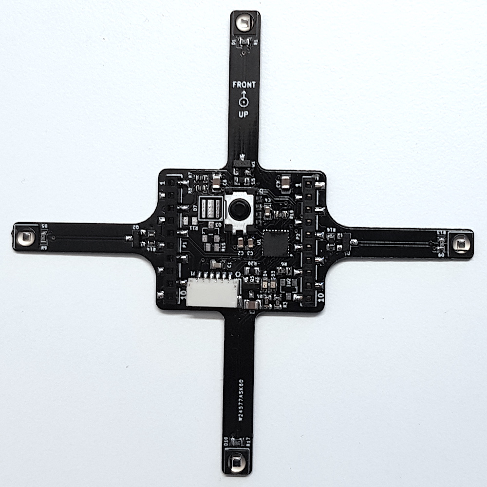
The Active marker deck is designed to go on top of the Crazyflie and has four arms with one LED each. The arms are as long as possible to maximize the signal/noise ratio in the cameras, while still short enough to be protected from crashes by the motors. There is a STM32 F0 on the deck that takes care of the LEDs and handling of IDs and the main Crazyflie CPU does not have to spend any time on this.
The status of the deck is that the hardware is fully functional (we might want to move something around before we produce it though) and that there is a basic implementation of the firmware. IDs are assigned to the markers using parameters in the standard parameter framework in the client or from a script.
We will start production of the deck in the near future and it will be available in the store this autumn. Qualisys added support for rigid bodies using active markers in V2019.3 of the QTM tracking software.
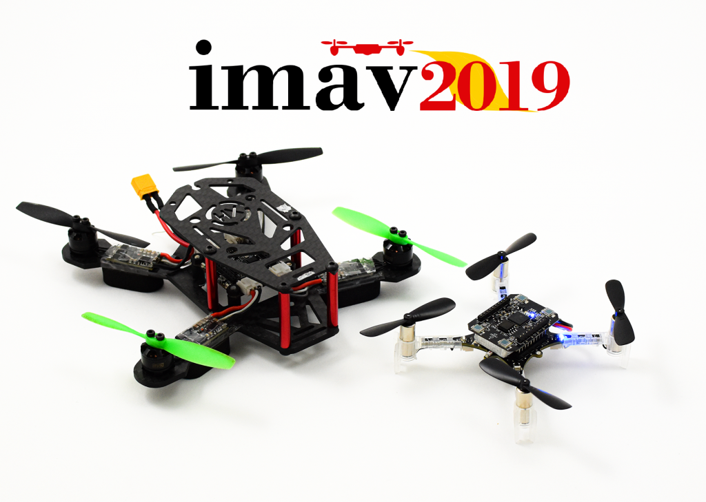
The Crazyflie Bolt and the Crazyflie 2.1 with the lighthouse deck are coming to Madrid!
Only one week away until the start of the big Bitcraze Conference frenzy, with the first stop… Madrid! We will visit the Micro Air Vehicle Competition and Conference, which is a robotics event that is more specialized in (as the name implies) MAVs! So it should be right up our alley. This is the first time that we attend as Bitcraze, although the writer of this blog post has experienced fun times at the conference and the competition as a participant with her previous lab, the MAVlab.
The IMAV has been around for almost 12 years, starting in Toulouse, France in 2007. Although it initially mostly was held in various places in Europe, in 2016 into a more worldwide phenomenon by making it’s tribute in Beijing, China and Melbourne, Australia in 2018. It hosts a conference to which researchers can send their work in anything related to MAVs, from autonomous navigation, state estimation and design.
IMAV is mostly know for hosting big indoor and outdoor competitions for MAVs. The outdoor competitions can range from survey tasks to finding a hidden person or object. This year the focus will be on the delivery of packages from one place to another. The judges will look at how many packages that can be safely delivered and if the drone is able to detect certain objects in the outdoor environment. The indoor competition is oriented around the application of MAVs in a warehouse. They should be able to take off autonomously, monitor boxes in shelves and make an innovatory, and pickup packages to release them in their designated location. 40 teams of 28 universities will show their awesome implementation in these difficult tasks.
We will have a booth at the main company fair at the conference and indoor competition, and will also be present at the outdoor competition day as well. We will bring the lighthouse positioning system and show the awesome swarming demo we developed. Also we want to bring the new Crazyflie Bolt with us, which we are sure of that the regular IMAV crew will love. If you are at the IMAV between the 30th of September to the 4th of October, come by and say hello!
We are happy to announce that we have made new official releases of a number of our software components. The name of the release is 2019.09 and we have outlined the main changes below.
Crazyflie/Roadrunner firmware
Added support for the Crazyflie Bolt
Improved support for external positioning systems
Basic support for the Lighthouse positioning system
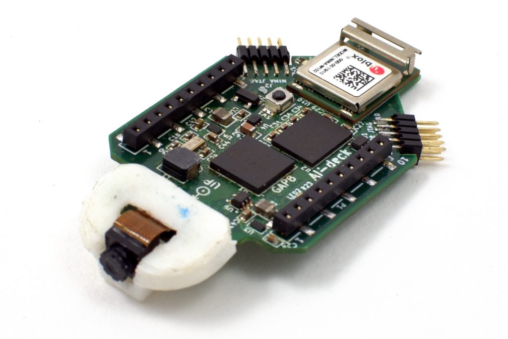
As pointed out in Daniele’s blog post about the PULP-DroNet we are collaborating on a AI-deck built around the new GAP8 RISC-V multi-core MCU. In the blog post you can find all the details around DroNet while here we will talk a bit about the AI-deck hardware. The AI-deck is similar to the PULP-Shield but with some optimizations. One of the HyperFlash memory spots has been removed, the communication interface slimmed down and a ESP32 (NINA module) has been added for WiFi connectivity.
Latest AI-deck prototype
So all together this a pretty good platform to develop low power AI on the edge for a drone.
Features:
GAP8 – Ultra low power 9 core RISC-V MCU
Himax HM01B0 – Ultra low power 320×320 greyscale camera.
512 Mbit HyperFlash and 64 Mbit HyperRAM
ESP32 for WiFi and more (NINA-W102)
2 x JTAG for GAP8 and ESP32
Currently we are doing the final testing of the hardware and hopefully we will launch production in the end of October. If production goes according to plan we hope we can offer it as an early access product just before X-mas. Make sure to come back and check the blog for more information about the progress as well as pricing.
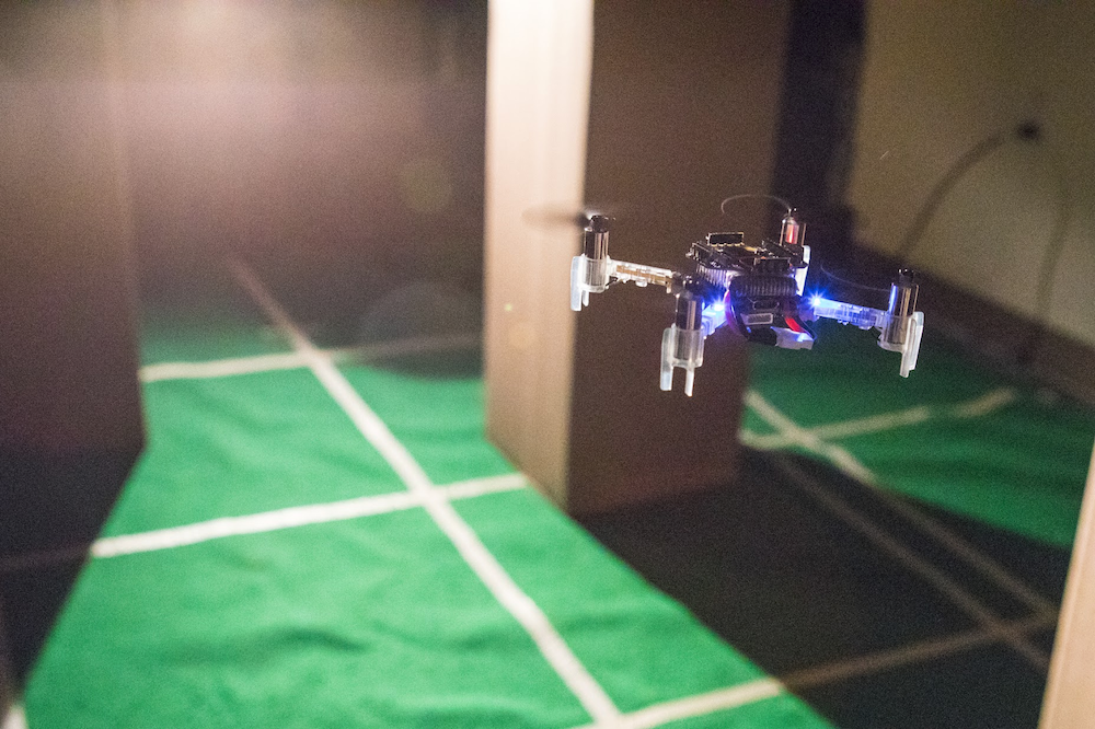
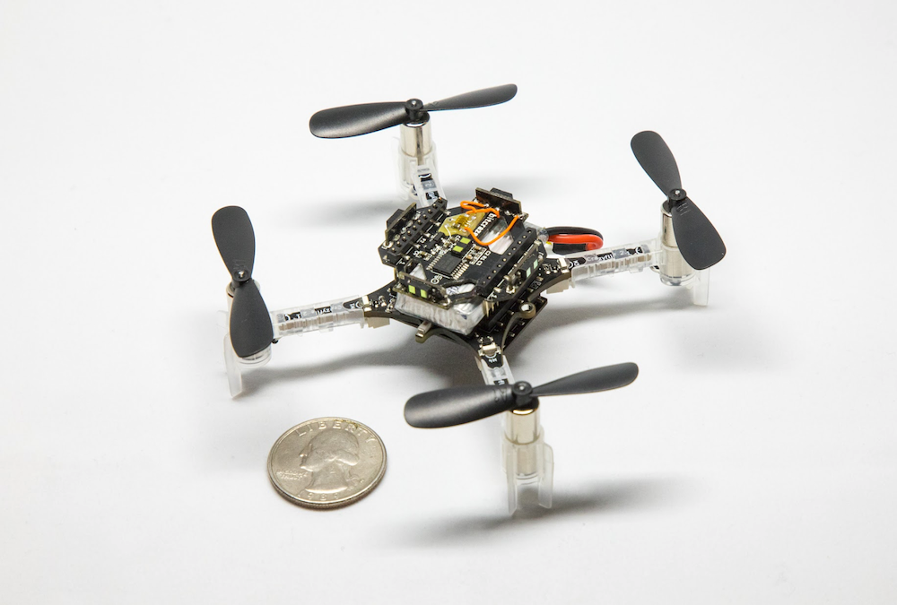
CrazyFlies are great for indoor applications, thanks to their maneuverability and ubiquitous character. Its small size, however, limits sensor quality and compute capability. In our recent work we present source seeking onboard a CrazyFlie by deep reinforcement learning. We show a general methodology for deploying deep neural networks on heavily constrained nano drones, using full 8-bit quantization and input scaling.
Our fully autonomous light-seeking CrazyFlie
Problem definition
Source seeking can be interesting in a variety of contexts. We focus on light seeking, as seen in nature. Many insects rely on light, either for survival or navigation. Light seeking in aerial robotics has many applications, such as finding the exit out of a dark room.
Our goal is to fully autonomously find a light source, using only the onboard Micro Controller Unit (MCU) and deep reinforcement learning.
Crazyflie configuration
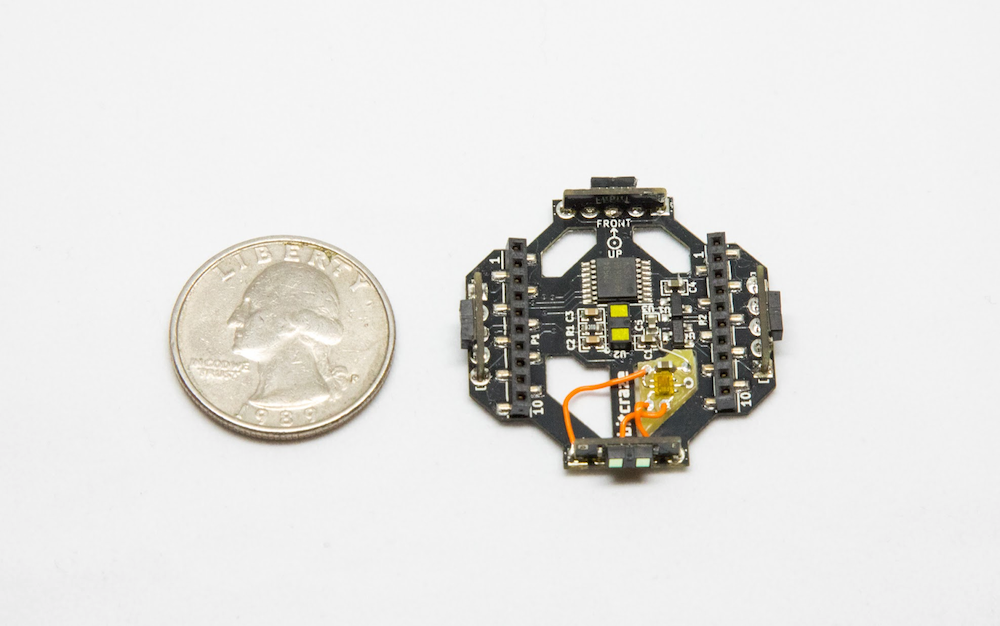
Our fully autonomous nano drone uses several standard and custom sensors. We use the multiranger and flowdeck for position control and obstacle avoidance.
The Multiranger deck with our custom light sensor
We add a custom light sensor, based on the Adafruit TSL2591 sensor. The custom light sensor nicely fits in the multiranger deck, adding little mass and inertia (total vehicle mass is 33 grams).
CrazyFlie 2.1 with multiranger, flowdeck and light sensor
Algorithm
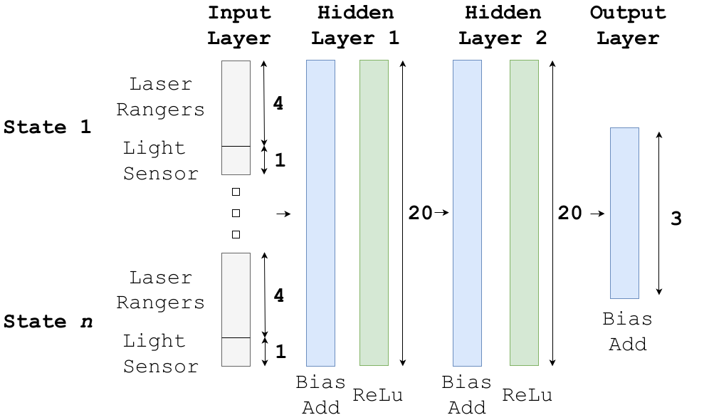
We use a deep reinforcement learning algorithm with a discrete action space. The neural network policy has laser rangers and light readings (current and past values) as input. The neural network tells the drone to rotate left, right or fly forward. We train a neural network with 2 hidden layers of both 20 nodes, featuring bias add and relu activation functions. The input layer is a vector with a length of 20 (4 states), which, compared to images, greatly reduces computational effort.
DQN policy architecture
Simulation and conversion
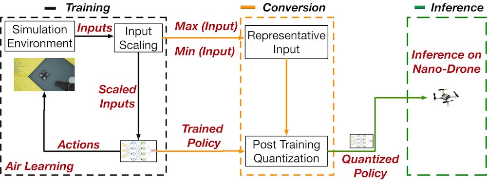
We train our agent in simulation using the Air Learning simulation platform, after which we fully quantize the neural network to 8-bit integers.
To maintain accuracy after quantization, we have come up with quantization innovations. Both input layer and all tensors in the network need to have a pre-defined [min,max] range in float32, to convert to 8-bit integers.
Air Learning pipeline
In the input layer, not all inputs have the same range. That is, a laser ranger can have values from 0 to 5 meters while our light sensor may return a value between 0 and 300 lux. To avoid this issue, we scale all inputs to the same range.
Additionally, the tensors in the network need to have an assigned [min,max] range for quantization. To achieve this, we input a range of representative input into the unquantized model, and read out the values of intermediate layers. With this strategy, we arrive at a 2.9x speed-up compared to float32 inference.
Implementation
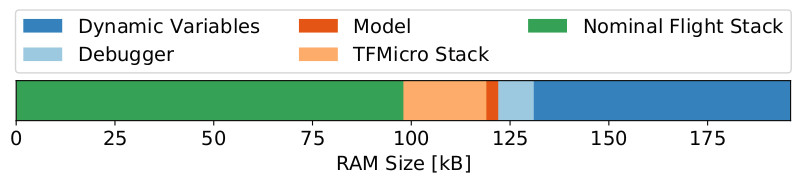
We use Tensorflow Lite to deploy our tensorflow models in C on the CrazyFlie. The TFMicro Stack, together with the actual model, almost completely fill up the available RAM.
RAM utilization on the CrazyFlie 2.1
The total amount of RAM available on the CrazyFlie 2.1 is 196kB, of which only 131kB is available for static allocation at compile time. The Bitcraze software stack uses 98kB of RAM, leaving only 33kB available for our purposes. The TFMicro stack takes up 24kB, thus leaving 9kB for the actual model (e.g., weights, bias terms).
We also analyzed CPU usage, and noticed a high amount of interrupts by the ‘stabilizer’ thread, i.e., the PID controllers. Because of these interrupts, inference of our model takes 46.4 times longer than it would have been without interruption.
Our quantized model is 3kB. If it were an FP32 model, it would have taken 12kB, which would not have fitted in the available memory. We were able to run inference at 4Hz, compared to the estimated 1.4Hz of the same but unquantized model.
In a practical sense, we noticed a decreased level of stability when increasing model size. Occasionally the drone would reboot randomly while flying. Possible causes for this behavior are RAM overflow and task scheduling problems in RTOS. Besides, we observed variation in performance loss after quantization. Some of our trained models would just keep rotating after quantization, while our final model demonstrates robust source seeking behavior. This degree of uncertainty can possibly be avoided using quantization aware training.
Finally, flying in a dark room without a position estimate can be challenging. The PID controllers heavily rely on information provided by the Flow Deck. This information is limited when little light is present while flying over a floor containing little features. To fix this, we added mats with texture on the ground, adding features and enabling stable flight in a dark room.
Flight tests
To validate our results in simulation, we created a cluttered environment with a light source. We randomly initialized the drone in the room, and hereby observed a success rate of 80% in a total of 105 flight tests. By varying the environment and initial drone position, we learned more about the inner workings of our algorithm.
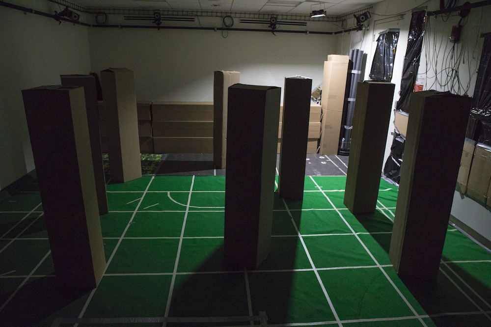
Experiment testing environment
We learned that the algorithm performs better with more obstacles, and that a closer initial position improves performance. Generally, source seeking far away from the source seems really hard. Almost no variation in source strength exists between different measurements, and the drone observes mostly noise.
Outlook
With our methodology, we were able to perform fully autonomous source seeking using deep reinforcement learning on a Cortex-M4 MCU. We hope our methodology will be applicable to other TinyML applications where resources are heavily constrained. Developing custom accelerators for a specific workload is time-consuming and expensive, while general purpose MCU’s are cheap and widely available. With our methodology, we unlock new applications for learning algorithms on heavily constrained platforms.
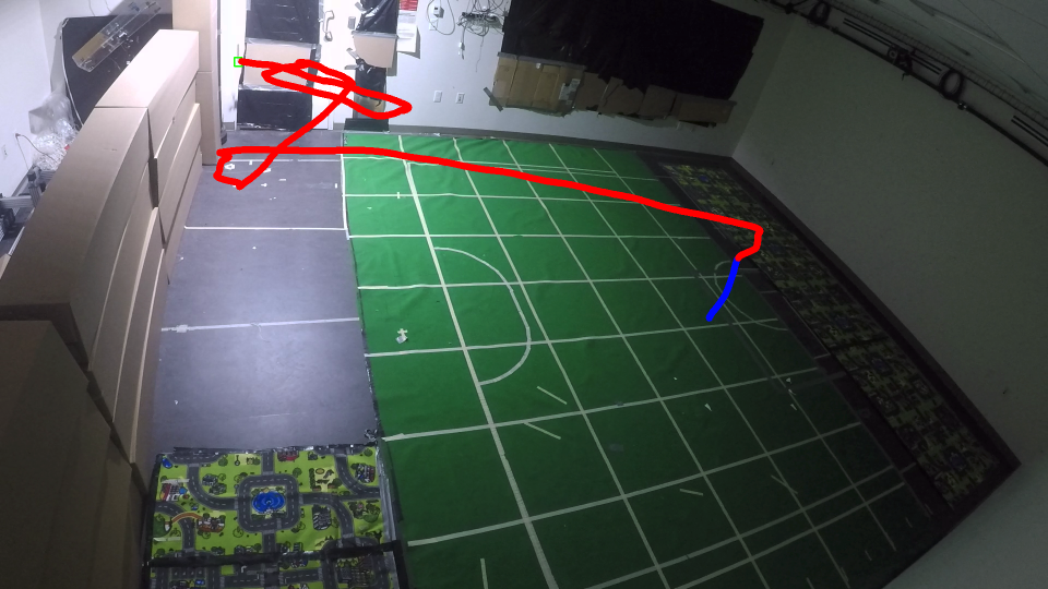
Direct path to source in empty room, blue = take-off
Over time the scope of Crazyflie has changed a lot. At first, Crazyflie was “just flying” with the only possible control was attitude (roll, pitch, yaw) and thrust setpoint sent from the Radio. Soon after, autonomous flight was investigated, first by implementing position controller outside Crazyflie and then, over time, moving position control on-board and sending position or trajectory setpoint to the Crazyflie. Now that the Crazyflie has good position control, the next step is to implement autonomous behavior and until now the most practical way is to do this from code running in an external computer. Similarly to what happened in the history of position control (first off-board and now onboard), it needs to be possible implement autonomous behavior in the Crazyflie itself. This blog post is about two newly implemented capabilities that will allow to implement automation in the Crazyflie firmware in an easy and maintainable way, namely the ‘App layer’ and the P2P communication.
App layer
The “App layer” is a term we have been using internally in Bitcraze to describe a set of functionalities that would allow to implement code in the Crazyflie. This includes the infrastructure to compile and maintain external code running in the Crazyflie as well as a set of API to control flight and behavior from C code rather than from radio communication.
Last week we implemented the first step of the App layer: the infrastructure part. It is now possible to build the Crazyflie firmware out-of-tree. This means that it is now possible, from a project, to point to the Crazyflie firmware folder and to compile a firmware from the project folder without touching the Crazyflie firmware folder. Practically it allows to create a git-repos implementing custom firmware code that has Crazyflie firmware as a sub-repos. This makes the maintenance of custom firmware code much easier than maintaining a branch of the Crazflie firmware as previously required.
A second piece that has been implemented is the app entry-point. It allows to start running code by just creating an “appMain()” function. The function will be called from a dedicated FreeRTOS task after the Crazyflie has initialized and started. This should make it much easier to get started.
For an example, we have extracted the multiranger push demo into a standalone git repos. This demonstrate the implementation of autonomous behavior using these new infrastructures.
Peer to Peer communication
The Crazyflie has been used for many research related to swarming, some examples are the crazyswarm project or the work done by Carnegie Mellon University. However, it is now time to turn it up a notch. On the forum and on the Github repository, there has been several request of enabling direct peer to peer communication to the Crazyflies. Now we finally found time to work on it and implement some basic functionality on the NRF and STM side of the firmware.
Currently, it is possible to send and receive a P2P packet in broadcast mode from the STM directly (see how to do this in the documentation). This enables data to be send from one Crazyflie to another with a maximum data size of 60 bytes. We were able to stress-test this with our test rig, by sending broadcast messages in a round-robin-kind of fashion, where the broadcast message was transferred through 10 Crazyflies in 10-20 ms. Even-though the current implementation is for now very minimal, we were able to fix some existing issues in the radiolink framework.
We will not stop there, as we are hoping to implement a communication system similar to how the CTRP protocol has been implemented. We are getting a lot of help by our active community members, so check out this github issue to be up-to-date with the current discussion.
For the last four years of doing my PhD at the TU Delft and the MAVlab, we were determined to figure out how to make a swarm/group of tiny quadcopters fly through and explore an unknown indoor environment. This was not easy, as many of the sub-challenges that needed to be solved first. However, we are happy to say that we were able to show a proof-of-concept in the latest Science Robotics issue! Here you can see the press release from the TU Delft for general information about the project.
Since we used the Crazyflie 2.0 to achieve this result, this blog-post we wanted to mostly highlight the technical side of the research, of the achievements and the challenges we had to face. Moreover, we will also explain the updated code which uses the new features of the Crazyflie Firmware as explained in the previous blogpost.
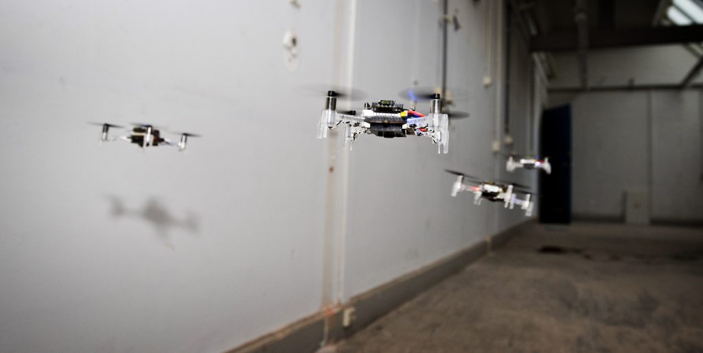
A swarm of drones exploring the environment, avoiding obstacles and each other. (Guus Schoonewille, TU Delft)
Hardware
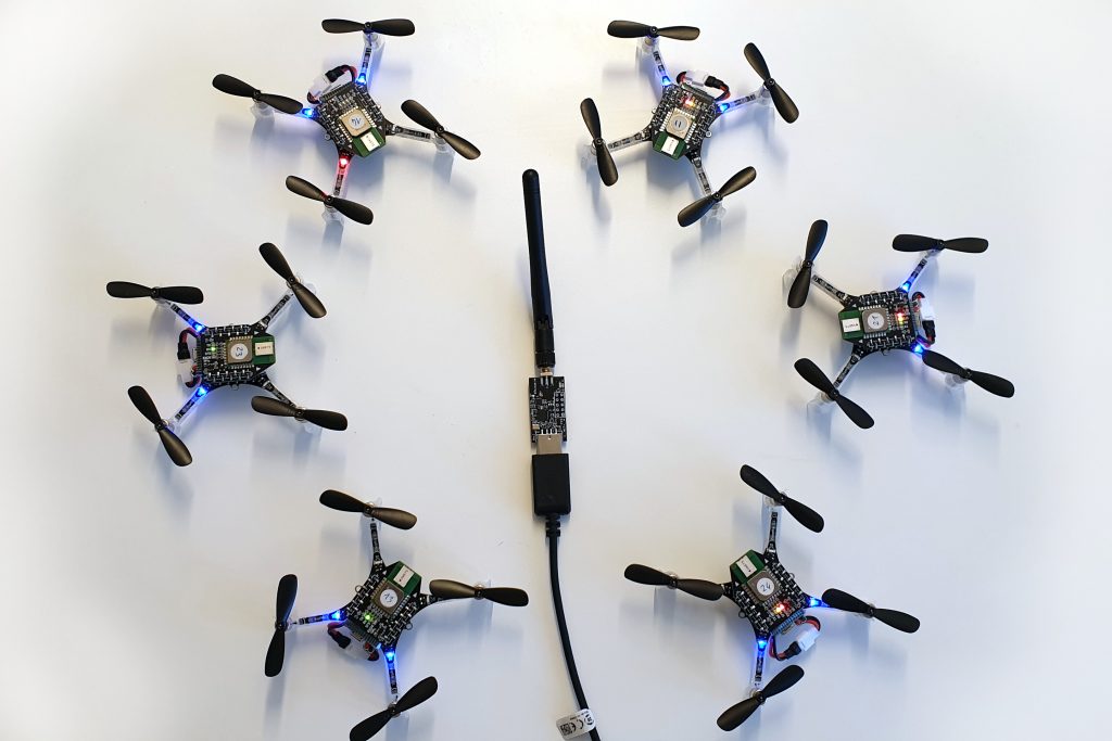
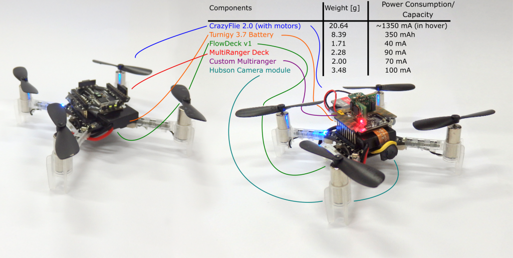
In the paper, we presented a technique called Swarm Gradient Bug Algorithm (SGBA), which borrows (as the name suggests) navigational elements from the path planning technique called ‘Bug Algorithms’ (see this paper for an overview). The basic principle is that SGBA is a state-machine with several simple behavior presets such as ‘going to the goal’, ‘wall-following’ and ‘avoiding other Crazyflies’. Here in the bottom you can see all the modules were used. For the main experiments (on the left), the Crazyflie 2.0’s were equipped with the Multiranger and the Flowdeck (here we used the Flow deck v1). On the right you see the Crazyflies used for the application experiment, were we made an custom Multiranger deck (with four VL53L0x‘s) and a Hubsan Camera module. For both we used the Turnigy nanotech 300 mAh (1S 45-90C) LiPo battery, to increase the flight time to 7.5 min.
With this, we were able to have 6 Crazyflies explore an empty office floor in the faculty building of Aerospace engineering. They started out in the middle of the test environment and flew all in different preferred directions which they upheld by their internal estimated yaw angle. With the multi-rangers, they managed to detect walls in their, and followed its border until the way was clear again to follow their preferred direction. Based on their local odometry measurements with the flowdeck, the Crazyflies detected if they were flying in a loop, in order to get out of rooms or other situations.
A little before half way of their battery life, they would try to get back to their initial position, which they did by measuring the Received Signal Strength Intensity of the Crazyradio PA home beacon, which was located at their initial starting position. During wall-following, they measured the gradient of the RSSI, to determine in which directions it increases or decreases, to estimate the angle back the goal.
While they were navigating, they were also communicating with each-other by means of broadcasting messages. Based on those measurements of RSSI, they could sense other Crazyflies approaching, which they first of all used for collision avoidance (by letting the low priority CFs move out of the way of the high priority CFs). Second of all, during the initial exploration phase, they communicated their preferred direction as well, so that one of them can change its exploration behavior to not conflict with the other. This way, we tried to maximize the explored area by the Crazyflies.
One of those experiments with 6 Crazyflies can be seen in this video for better understanding:
We also showed an application experiment where 4 crazyflies with the camera modules searched for 2 dummies in the same environment.
Challenges
In order to get the results presented above, there were many challenges to overcome during the development phase. Here is a list that explains a couple of the elements that needed to work flawlessly:
Single CF robustness: We used the Flowdeck v1, for the ‘deadlock’ detection and the basic velocity control, which was challenging in the testing environment because of low lighting conditions and texture. Therefore the Crazyflies were flying at 0.5 meters in order to ensure robustness. The wall-following was performed solely using the Multiranger. This was tested out in many situations and was able to handle a lot of type of obstacles without any problem. However the limited FOV of the laser range finder can not detect all types of obstacles, for instance thin ones or irregular ones such as plants. Luckily these were not encountered in the environment the Crazyflies flew in, but to increase robustness, we will need to consider adding a camera to the navigational drive as well.
Communication base-station. SGBA by essence only needs one base-station Crazyradio PA, since all the behavior is completely on board. However, in order to show results in the paper, it was necessary for the CF to communicate information back, like odometry, state and such. As this was a two way communication (CFs needed RSSI to get back) each Crazyflie needed 1 base-station. Also, they all needed to be on different channels to avoid package collisions and RSSI accumulation.
Communication Peer to Peer. At development time, P2P didn’t exist yet, so we had to implement broadcast communication between the Crazyflies. Since the previous pointer required them to listen on different channels, the NRF had to be configured to send separate broadcast messages on all those channels as well. In order to time this properly, the home beacon had to sync the Crazyflies accordingly by sending out a timer. Even so, the avoidance maneuvers were done very conservatively to try to prevent inter-drone collisions.
Many of the issues, especially the communication challenges, will be solved with the updated code implementation as explained in the next section.
Updated code
The firmware that the Crazyflies used to fly in the experiments showed in the paper, can all be found in this public repository. However, the code is based quite an old version the current Crazyflie firmware, as it was forked almost a year ago. The implementation of the SGBA state machine and the P2P broadcasting were not generic enough to integrate this back to the development cycle, therefore the current code is only suitable for the old Crazyflie 2.0.
Therefore, we developed two major changes in the latest firmware which will make it much easier for me (and other ideas as well we hope!) to implement SGBA and the P2P communication in a way that should be compatible with any version of the firmware (and hardware) from here and on. We implemented SGBA as an app-layer and also handled all the broadcast messaging directly from this layer as well. Please check out this Github repository with this new app layer implementation of SGBA.
This week we are exhibiting at IROS in Macau. We are running our fully autonomous demo based on the Lighthouse positioning technology and charging pads. We also have brought some prototypes to show, for instance the Crazyflie Bolt, the AI deck and the Active marker deck. You can read more about the demo at the IROS 2019 page.
We’d love to hear what you are working on, discuss issues, possibilities or new products. If you are at IROS, drop by our booth (B34) and say hi!
Lighthouse yaw
We have not only prepared for IROS, we have also been working on improving the lighthouse positioning system. Recently we added a (slightly hackish) solution for updating the yaw with data from the Lighthouse deck. This means that it is not necessary to start the Crazyflie facing the positive X direction when using the Lighthouse deck. The Crazyflie will understand its heading and act accordingly.
Two Crazyflies facing a random direction, take off and rotate to yaw=0.
We are also working on integrating the Lighthouse deck in a better way in the kalman filter. If everything goes according to plan, it will enable a Crazyflie to fly with only one base station, and be more robust when using two base stations.
We talked about it in a previous post, it is more than time to implement a higher abstraction layer for the Crazyflie firmware to make it easy to implement custom automations and programs on top of the flying platform. In this post we will try to explain the state of the art and where we are thinking of heading. This is mostly a request for comments and we are creating a github ticket to discuss about it.
DELFT – Zwerm Drones TU Delft. – FOTO GUUS SCHOONEWILLE
The out-of-tree build and P2P API presented in the previous post is a great start: it allows to make project on top of the Crazyflie firmware that can easily be maintained over time and to communicate directly between Crazyflie without having a PC in the loop. Though we have not completely solved or documented the API that can be called by the programs written on top of the Crazyflie, this is what the APP-layer is supposed to provide.
The current plan for the app layer is to make the same functionality that is available in the Python crazyflie lib API, accessible from within the Crazyflie firmware, using similar API calls. This way we get the possibility of prototyping functionality in python code on a remote machine, and when it is working, easily convert it to an app onboard. This is already implemented, in part, for the log and param API as well as for the low level parts of the commander. It has enabled us to write programs like the multiranger push demo and SGBA from Kimberly’s paper. The API is not yet documented properly and the function calls do not look like the ones on the python lib side at this time, but our intention is to converge the APIs over time.
We think that having the same level of functionality for Log, Param and Commander within a Crazyflie app, as in the python API, will already allow to implement a lot of onboard programs much more easily than has been possible until now. If there is anything else you think would be interesting to develop in this field, do not hesitate to drop a comment in this post or in the github issue.
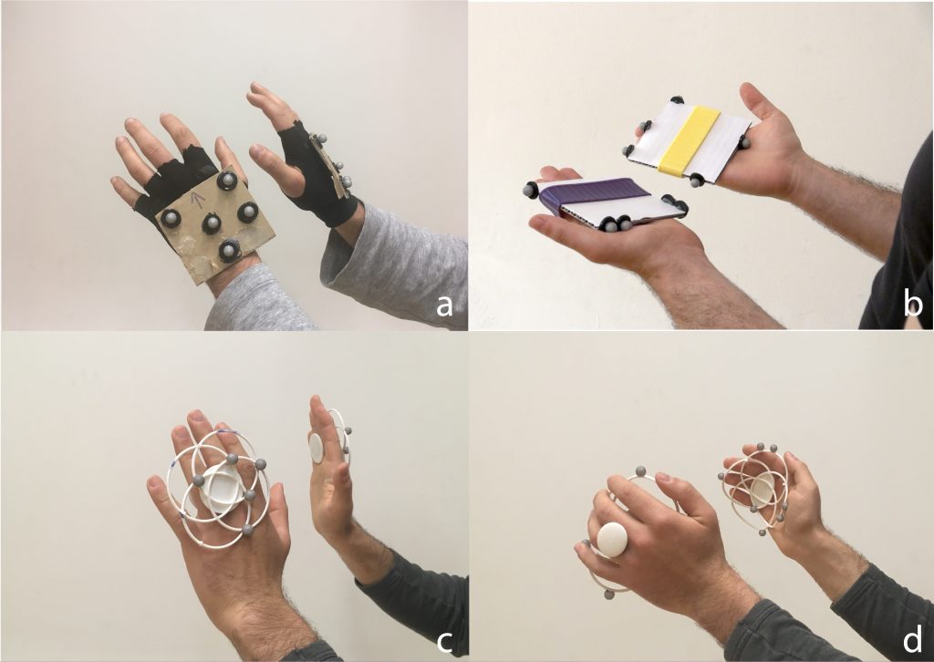
This week we have a guest blog post from Joseph La Delfa.
DroneChi is a Human Drone interaction experience that uses the Qualisys motion capture system that enables the Crazyflie to react to movements of your body. At the Exertion Games Lab in Melbourne Australia, we like to design new experiences with technology where the whole body can be the controller and is involved in the experience.
When we first put these two technologies together we realised two things.
It was super easy to keep your attention on a the drone as it flew around the room reacting to your movements.
As a result it was also really easy to reflect on and refine ones own movements.
We thought this was like meditation meditated by a drone, and wanted to investigate how to further enhance this experience through design. We thought the smooth movements were especially mesmerising and so I decided to take beginner Tai Chi lessons; to get an appreciation of what it felt like to move like a Tai Chi student.
We undertook an 8 month design program where we simultaneously designed the form and the interaction of the Crazyflie. The initial design brief was pretty simple, make it look and feel light, graceful and from nature. In Tai Chi you are asked all the time to imagine a flower, the sea or a bird as you embody its movements, we wanted to emulate these experiences but without verbal instruction. Could a drone facilitate these sorts of experiences through it’s design?
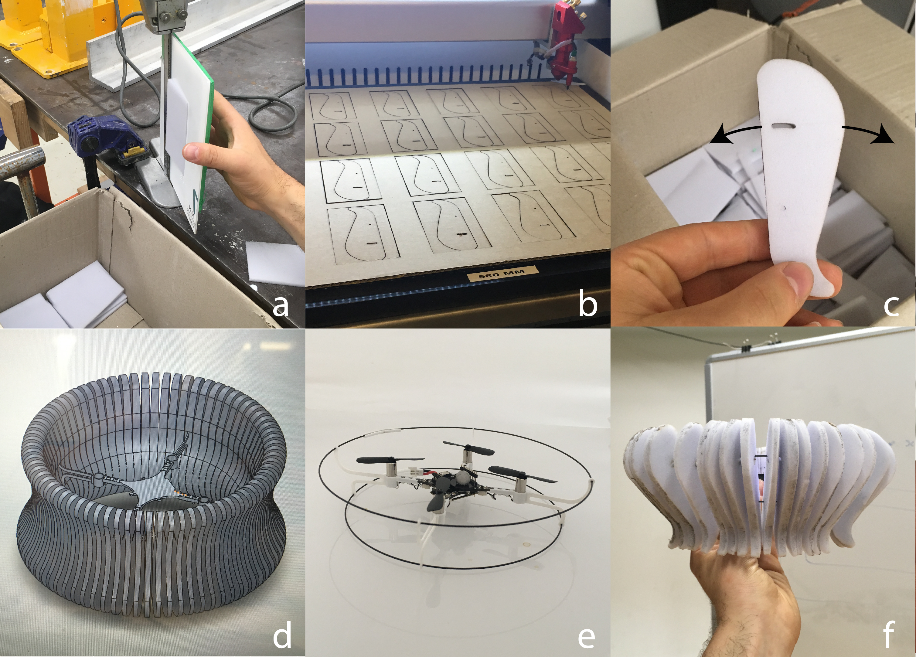
We will present a summarised version of how the form and the interaction came about. Starting with a mood board, we collated radially symmetrical forms from nature to match a drone’s natural weight distribution.
We initially went with a jelly fish, hoping to emulate their “push gliiide” movement by articulating laser cut silhouettes (see fig c). This proved incredibly difficult, after searching high and low for a foam that was light enough for the Crazyflie to lift, we just could not get it to fly stable.
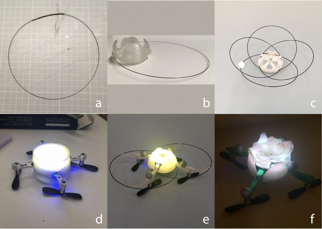
However, we serendipitously fell into the flower shape by trying to improve how we joined the carbon rods together in a loop (fig b below). By joining them to the main hull we realised it looked like a petal! This set us down the path of the flower, we even flipped the chassis so that the LED ring faced upwards (cheers to Tobias for that firmware hack).
Whilst this was going on we were experimenting with how to actually interact with the drone. Considering the experience was to be demonstrated at a major conference we decided to keep the tracking only to the hands, this allowed quick change overs. We started with cardboard pads, experimented with gloves but settled on some floral inspired 3D printed pads. We were so tempted to include the articulation of the fingers but decided against it to avoid scope creep! Further to this, we curved the final hand pads (fig d) to promote the idea of holding the drone, inspired by a move in Tai Chi called “holding the ball”.
As a beginner practicing Tai Chi I was sometimes overwhelmed by the number of aspects of my movement that constantly needed monitoring, palms out, heel out, elbow slightly bent, step forward etc. However in brief moments it all came together and I was able to appreciate the feelings of these movements as opposed to consciously monitoring them. We wanted this kind of experience when learning DroneChi so we devised a way of mapping the drone to the body to emulate this. After a few iterations we settled on the “mid point” method as seen below.
The drone only followed the midpoint (blue dot above) if it was within .2m of it. If it was outside of this range it would float away slowly from the participant. This may seem like a lot, but with little in the way of visual guidance (eg a laser pointer or an augmented display) a person can only rely on the proprioceptive feedback from their own body. We used the on board LED ring on the drone to let the person know at least when they are close, but that is all the help they got. As a result this takes a lot of concentration to get right!
In the end we were super happy with the final experience, in the study participants reported tuning into their bodies when using the drone, as well as experiencing a unique sort of relationship to the drone; not entirely like a pet and also like an extension of the body. We will be investigating both findings from the study through the design and testing of a new system on the Crazyflie. We see this work contributing to more intimate designs for human drone interactions as well as a being applicable to health contexts such as rehabilitation.
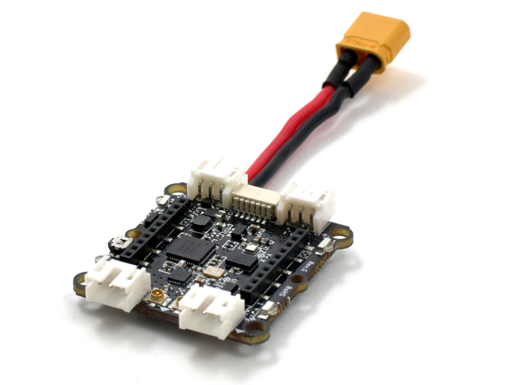
After a couple of delays we are happy to announce the Crazyflie Bolt is now stocked and ready to ship out. For those of you that are new to the Bolt, it is basically a Crazyflie 2.1 control board, but built to fit a bigger package. We have blogged about it a couple of times before, so if you would like to catch up you can start from the first idea, to maturing and finally changing name from RZR to Bolt. Another way to describe the Bolt is: Crazyflie 2.1 + Big-quad deck in one which doesn’t hog any deck expansion pins. Thus combinations such as Bolt + Led-ring + Lighthouse-4 is now possible or e.g. Bolt + Flow v2 + LPS.
Keep in mind that the Bolt is an early access product so you will most likely have to dig in to the code to hard-code PID-tuning parameters etc. Also trowing a warning finger, heavier drones can be very dangerous so be sure to keep safe!
The Crazyflie Bolt is delivered as a stand alone control board. Frame, motors, propellers and battery needs to be added, for details check out the wiki. Unfortunately we don’t have a good reference kit to recommend at the moment. If you happen to have built a good one, please share.
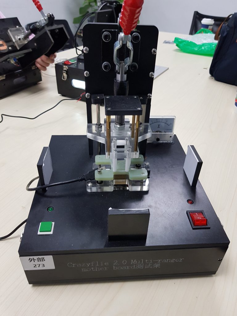
We are currently finishing production test design for a couple of expansion decks and we figured we never wrote about it and about the more general board production process. In this blog post we wanted to talk a bit about how we test boards in the productions phase, taking as an example the forthcoming active marker deck.
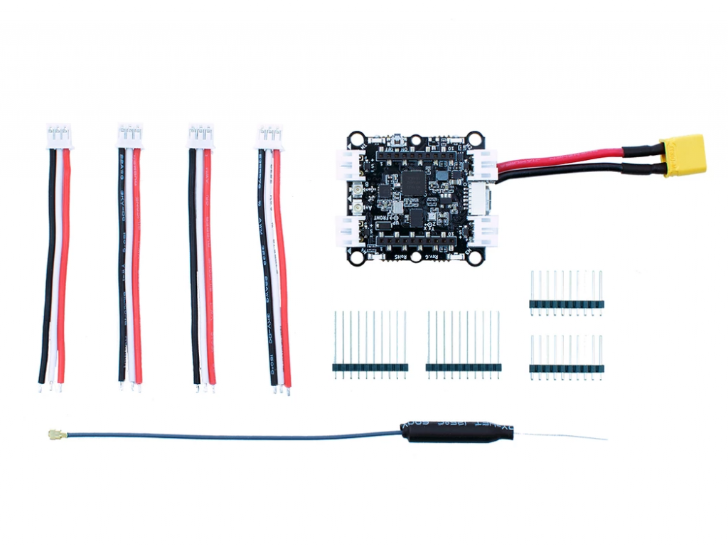
The active marker deck
When finalizing an electronic board, we send to the manufacturer documentation that allows to manufacture & assemble a, hopefully, functional board. Although we assume that the individual components are in working order, the problem is that the assembling is not always perfect, so we need to check that everything we do is actually working,. This is what the production test is solving.
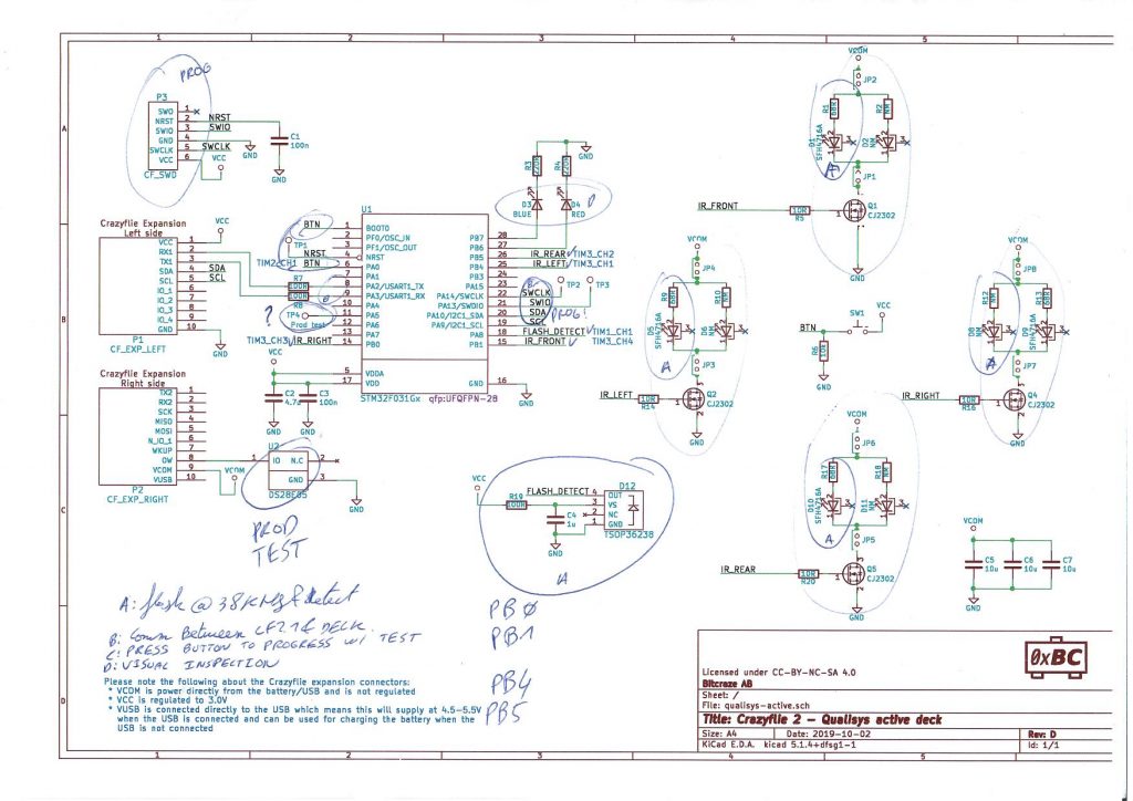
The first thing is to find out what to test, for that we need a strategy. The strategy we have been using is to test every step where we have modified or work on: for example we will test all the connections we have soldered in the manufacturing process. We will normally not test all the functionalities of ready-made module. For example, following this strategy, we will usually test all communication interface we have cabled, but we will not test all functionalities of a microcontroller we solder on the board, these are deemed to be already tested and working by the microcontroller manufacturer. This step usually end up with an annotated schematic:
Annoted schematics of ActiveMarker Deck
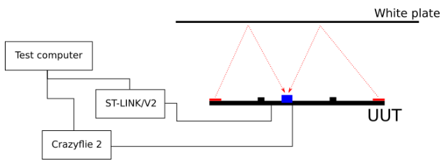
Once we know what to test and roughly how to test it, we document a test rig that will be able to run the tests automatically. Some tests are generic and applicable to all our boards, for example we do test voltages with a multi-meter on every board that has a regulator. Some tests are very board specific. For example, for the active marker deck we want to test IR LEDs and an IR detector, we define a test rig that has reflector to reflect the LED to the detector and we will use the onboard detector to test the LEDs:
Simple block diagram of the test rig for the ActiveMarker Deck
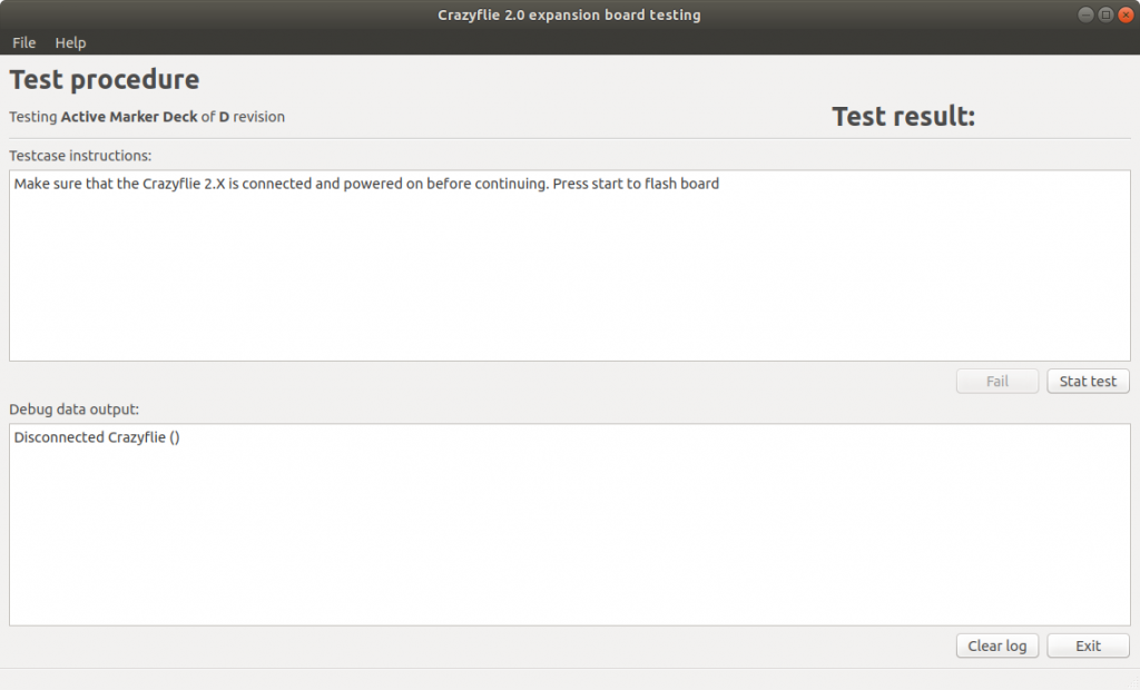
We are normally using a Crazyflie on all our test rig, since it is usually possible to test all functionality from the deck port. We also try as much as possible to integrate the test software into the real software. For the active marker deck it meant adding 38KHz modulated output mode to the LEDs in order to emit a signal detectable by the detector, which will make it to the final firmware. Finally, we have a test software, running on the test computer, that uses the Crazyflie python lib to talk to the Crazyflie and run the test. The last step of all the test is to write the deck One Wire identification memory so that it can be detected by a Crazyflie.
Screenshot of the test program for the test engineer
From these specification, the manufacturer can then build a test rig and start testing boards, non-passing board will be re-worked until they pass or discarded.
Test rig for the Multi-ranger expansion deck
What we have learned in our years at Bitcraze is that testing phase is the most important part of the development process of PCB. Therefore, the earliest we already start thinking about the production tests in the board design, the more smooth the final phase of production of our new products will be.
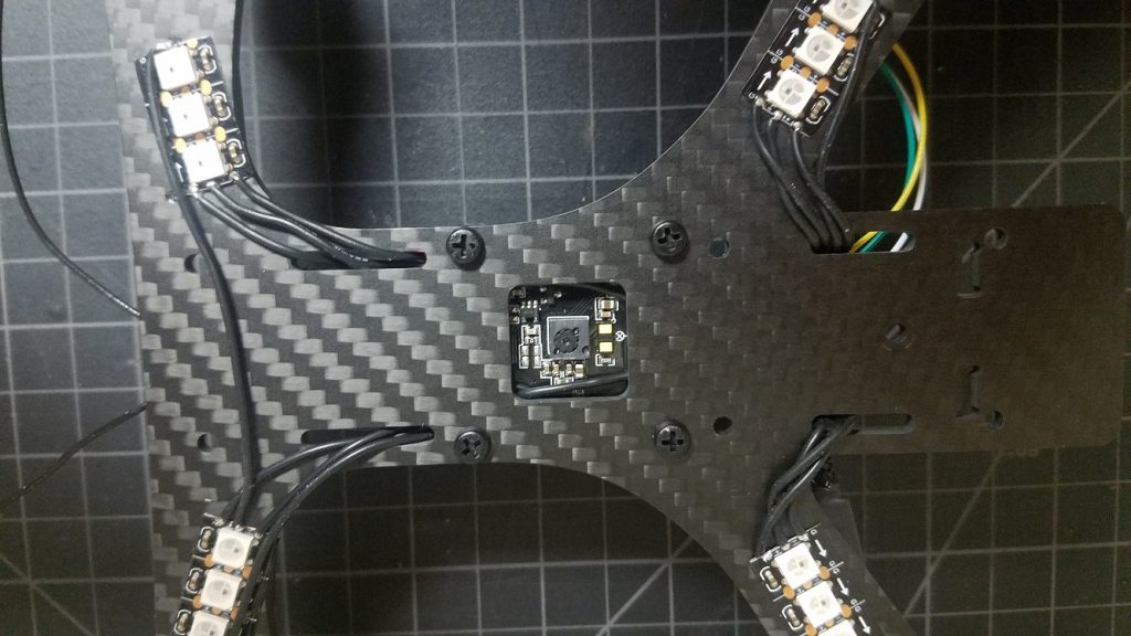
I started working with the Crazyflie 2.0 in 2015. I was interested in learning how to program a quadcopter, and the open-source nature of the Crazyflie’s hardware and software was the perfect starting point.
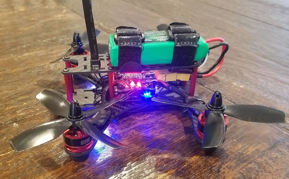
Shortly after, I discovered the world of FPV and the thrill of flying with a bird’s eye view. My journey progressed from rubber-banding an all-in-one camera/VTX to my Crazyflie, to building a 250mm racing quad (via the BigQuad deck), and into the world of Betaflight (including bringing Betaflight support to the Crazyflie hardware).
Naturally, the announcement of the Bolt (then known as the RZR) piqued my interest, and the folks at Bitcraze graciously allowed me early hands-on with the product.
This post details my progress towards building out a FPV-style drone on top of the Crazyflie Bolt.
Component List
The FPV community has come a long way since 2015. What once was a very complicated process is now well documented and similar to building a PC (well, with some soldering). For latest details on the specifics of building FPV drones, I recommend resources such as Joshua Bardwell or the r/Multicopter subreddit.
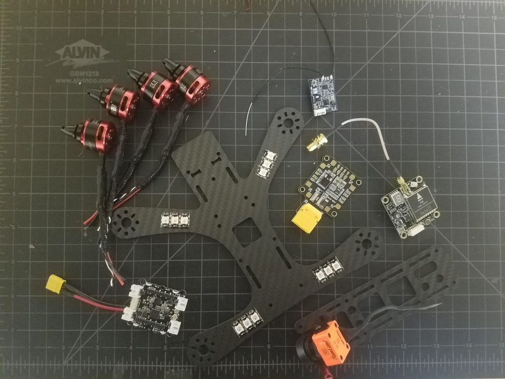
Turns out I had enough components lying around for a 4-inch (propeller diameter) build based on 3S (3 cell) LiPo batteries. Again, there’s nothing special about these parts (in fact they’re all out of date). Take this list as a guide, and do your own research.
PDB (Power Distribution Board): This is a circuit board that produces regulated voltages from an unregulated LiPo battery. The Bolt has built-in regulators but is only rated up to an 8A current draw per motor. My 4 inch propellers will certainly draw more than 8A, and so an external PDB is required (plus having dedicated 12V and 5V supplies is nice for peripherals).
4x DYS 1806 Brushless Motors: Brushless motors use magnetic pulses to rotate a motor bell (distinct from brushed motors found on the regular Crazyflie).
4x DYS 20A BLHeli_S ESCs (Electronic Speed Controller): This is a piece of circuitry that accepts a logic-level control signal and applies direct battery power to motor coils to make a brushless motor spin. They have to be rated for the current draw expected by the battery+propeller combination.
Tweaker (by Shendrones) Frame: I’ve been wanting to build a quad around this frame, and the large square hole is interesting for the Bolt (more on that later). One thing to keep in mind is this is an ‘H’ style frame. That is, it’s longer than it is wide, so flight will not be perfectly symmetrical. If you’re interested in building a larger Crazyflie and not so interested in FPV, you’ll definitely want a symmetrical ‘X’ style frame.
Camera + VTX: For a full FPV setup, you’ll need a camera and a video transmitter. For the most part these run completely independently of the flight controller and so I’ll omit them from this article — what I’ve shown in the picture above is horribly out of date anyway.
RX: Radio receiver. For longer range flights and reduced latency it may be a good idea to use an external radio and UART-based receiver with diversity antennas. However, some specific work went in to the Bolt’s antenna design, so I’ll be sticking with the on-board NRF51 and external antenna.
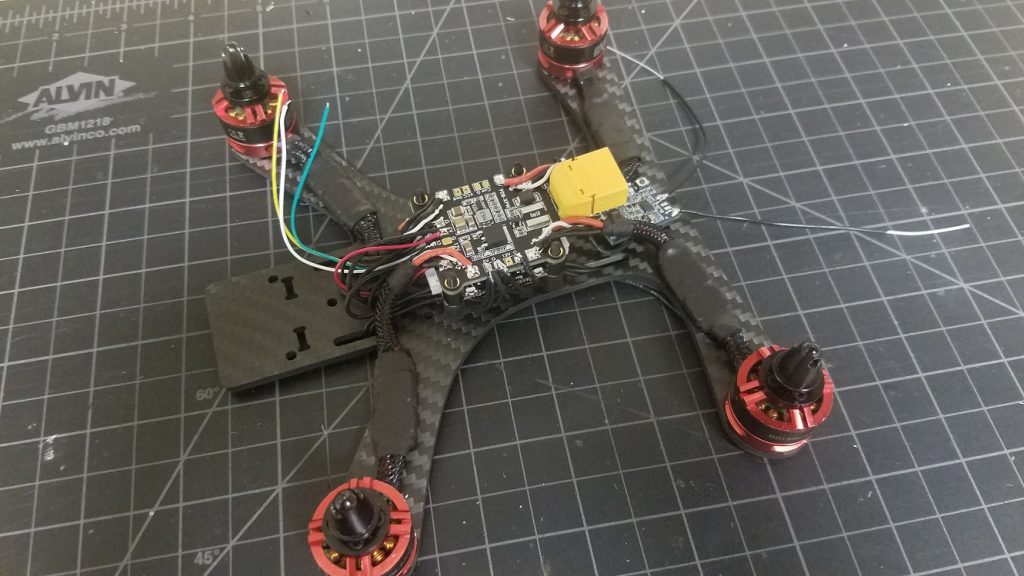
Again, there are hundreds of fantastic guides on the web that detail how to build an FPV quadcopter. Instead of trying to create another, here are some notes specific to my Bolt build.
Expansion Decks
Since the Bolt is pin compatible with the Crazyflie, I thought it would be interesting to try and take advantage of a couple existing Crazyflie expansion decks in my build: The LED Ring Deck, the Flow Deck v2, and the Micro SD Card Deck.
The LED Ring Deck
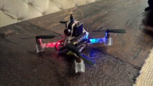
The LEDs were the most hands-on feature to enable. Rather than simply attaching the LED ring inside the frame, I mounted a series of WS2812B lights to the underside of my frame’s arms. The LED Ring Deck consists of 12 LEDs connected in series — so I put three LEDs on each arm of the frame and wired them up in a daisy-chain.
Finally, I soldered the lead to IO_2 (the same that’s used by the LED Ring Deck) on a Breakout Deck.
Since this isn’t the official LED Ring Deck, there’s no OW memory ID. The deck must be force-enabled by specifying a compile flag in your tools/build/make/config.mk file:
CFLAGS += -DDECK_FORCE=bcLedRing
With the custom firmware, the under-arm LEDs work just like the LED Ring Deck (other than the lack of front-facing LEDs).
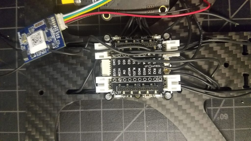
Micro SD Card Deck
Most popular flight controllers feature flash storage or SD card slots for data logging. The FPV community uses storage to log sensor data for PID tuning and debugging. Naturally, this deck is a good fit on my Bolt build, and requires no additional modification.
Flow Deck (v2)
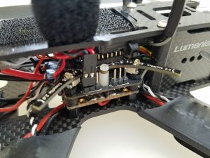
Remember my interest in the square cutout on my frame of choice? That, and my unorthodox choice to mount the Bolt board below my PDB, means I can theoretically use the bottom-attached Flow Deck to achieve some lateral stabilization while close to the ground. In theory, the VL53L1x ranger should work outdoors thanks to its usage of 940nm light as opposed to 850nm.
Note: This photo also shows the daisy chain wire connecting banks of LEDs in series
Other Build Tips
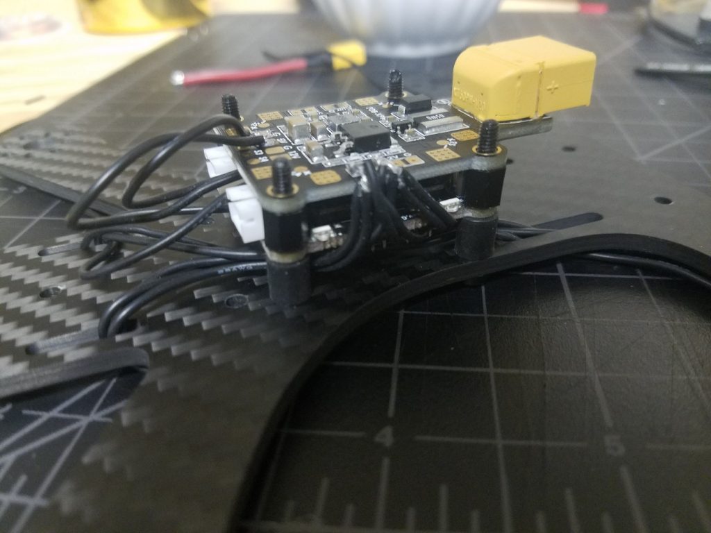
It’s good practice to soft mount flight controllers to minimize transferring motor/prop vibrations into the IMU. I used these to isolate the flight controller from the frame — not perfect, but better than a rigid mount.
The receiver antenna must be mounted clear of the carbon fiber frame and electronics. I like to use a heavy duty zip tie and attach the antenna with heat shrink.
The Bolt can be powered from a 5v regulator on your PDB, but if you want to take advantage of the VBat sensor it should be powered from the raw battery leads instead. However, most ESCs support active breaking (ability to slow/stop the propellers on demand). Active breaking is known to produce a lot of back-voltage, which can damage some circuits. To be safe, since I’m using a 3S battery (12.6V when fully charged, 11.1V when depleted) I chose to power the Bolt off a regulated 12V supply from my PDB. This way, the PDB’s regulator will filter out voltage spikes and help protect the Bolt. Readings won’t be accurate at the higher range, but what really matters for a voltage sensor is to know when to land.
Results
It works! There is work needed to improve flight, though:
Control tuning is required. The powerful brushless motors respond much quicker than brushed motors, and so many of the PID and/or Kalman parameters are too aggressive or just non-optimal.
Stabilization with the Flow deck does not work — I haven’t spent much time debugging but my guess is it’s either due to the Kalman tuning, or problems with the VL53L1x depth working outdoors (which also impacts the flow measurements)
Betaflight Support: Betaflight has no driver for the BMI088 IMU used on the Crazyflie Bolt or the Crazyflie 2.1.
Safety Features: Brushless quads are very dangerous and can cause serious injuries. It’d be good to implement a kill-switch and a more aggressive failsafe in the firmware to prevent flyaways.
All in all, this was an enjoyable project and I’m excited to see some autonomous brushed quads coming out of the Crazyflie community!
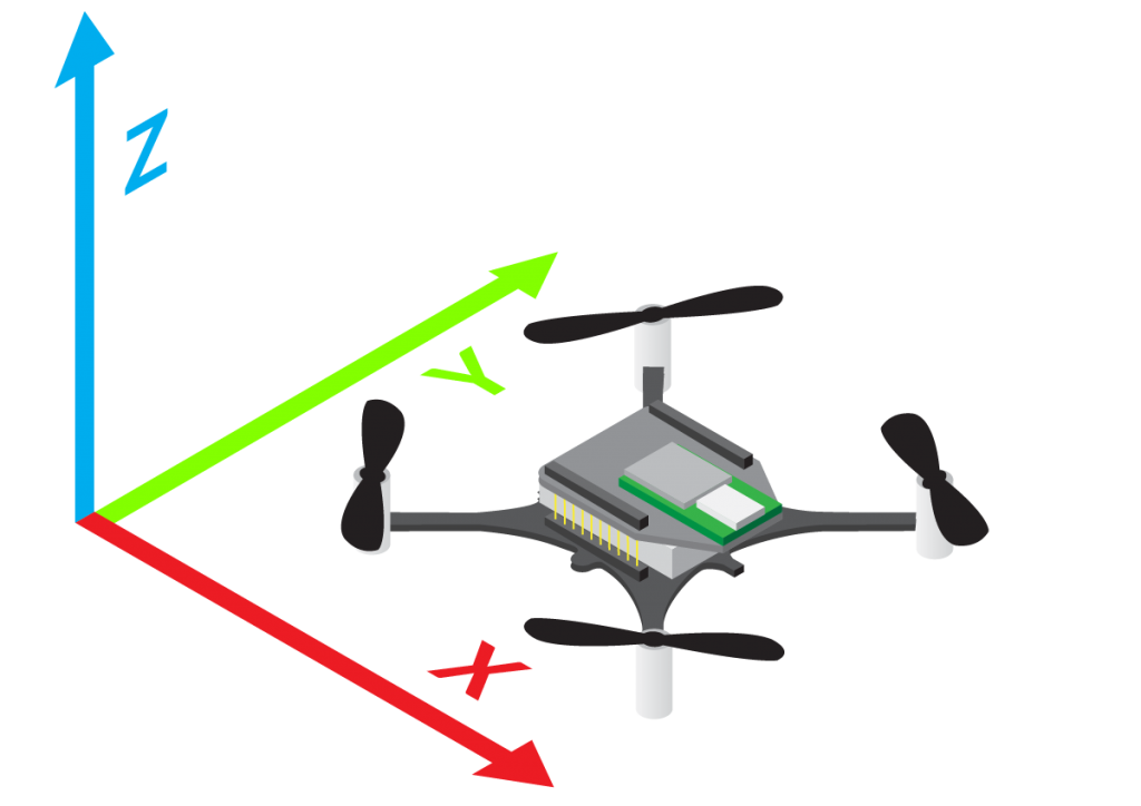
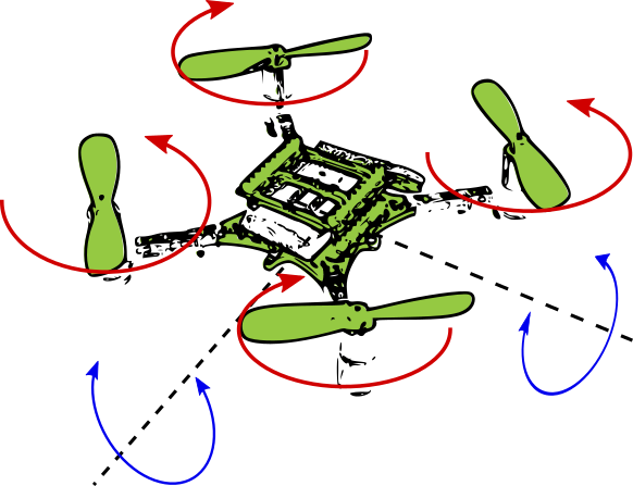
How does a Crazyflie manage to fly and stay in the air in the first place? Many of us tend to take this for granted as much research tend to happen on the application level. Although we try to make the low level elements of flight as stable as possible, it might happen that whatever you are trying to implement on the application level actually effects the Crazyflie on the low level controls and estimation. We therefore would like to focus a little bit on the inner-workings of the autopilot of the Crazyflie, starting with state estimation. The state estimation is part of the stabilizer loop in the Crazyflie, an overview of is was made in a previous blog post.
State estimation is really important in quadrotors (and robotics in general). The Crazyflie needs to first of all know in which angles it is at (roll, pitch, yaw). If it would be flying at a few degrees slanted in roll, the crazyflie would accelerate into that direction. Therefore the controller need to know an good estimate of current angles’ state and compensate for it. For a step higher in autonomy, a good position estimate becomes important too, since you would like it to move reliably from A to B.
There are two types of state estimators in the crazyflie firmware, namely a Complementary Filter and an Extended Kalman Filter.
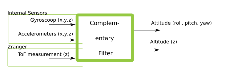
Complementary Filter
The complementary filter is consider a very lightweight and efficient filter which in general only uses the IMU input of the gyroscope (angle rate) and the accelerator. The estimator has been extended to also include input of the ToF distance measurement of the Zranger deck. The estimated output is the Crazyflie’s attitude (roll, pitch, yaw) and its altitude (in the z direction). These values can be used by the controller and are meant to be used for manual control. If you are curious how this code is implemented exactly, we encourage you to checkout the firmware in estimator_complementary.c and sensfusion6.c. The complementary filter is set as the default state estimator on the Crazyflie firmware.
Schematic overview of inputs and outputs of the Complementary filter.
Extended Kalman Filter
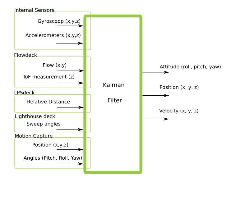
The (extended) Kalman filter is an step up in complexity compared to the complementary filter, as it accepts more sensor inputs of both internal and external sensors. It is an recursive filter that estimates the current state of the Crazyflie based on incoming measurements (in combination with a predicted standard deviation of the noise), the measurement model and the model of the system itself. We will not go into detail on this but we encourage people to learn more about (extended) Kalman filters by reading up some material like this.
Schematic overview of inputs and outputs of the Extended Kalman Filter
Shortly said, because of the more state estimation possibilities, we preferred the Kalman filter in combination with several decks: Flowdeck, Loco positioning deck and the lighthouse deck. If you look in the deck driver firmware (like for instance this one), you see that we set the required estimator to be the Kalman and that is of course because we want position/velocity estimates :). Important though is that each input of the measurement effects the quality of the position, as positioning of the Lighthouse deck (mm precision) is much more accurate that the loco positioning deck (cm precision), which has all to do with the standard deviation of the measurement of those values. Please check out the content of estimator_kalman.c and kalman_core.c to know more about the implementation. Also good to know that the Kalman filter has an supervisor, which resets if the position or velocity estimate is gets out of hand.
Of course this blogpost does not show the full detailed explanation of state estimation, but we do hope that it gives some kind of overview so you know where to look if you would like to improve anything. The Kalman filter can easily be extended to accept more inputs, or the models on which the estimates are based can be improved. If you would like implement your own filter, that would be perfectly possible to do so too.
It would be great if you guys could share your thoughts and questions about the state estimation on the crazyflie on the forum!
Two weeks ago, we had a blogpost about the state estimators that are available within the Crazyflie. So once the Crazyflie knows where it is, it would need to be determined where it wants to go, by means of the high level commander (implemented as part of the crazyswarm project) or set-points given by CFclient or directly from scripts using Crazyflie python lib. But exactly how would the crazyflie get to those desired positions in the first place? The differences between the current state estimates and the desired state, will need to be transformed to inputs given to the motors. Unfortunately, quadrotors like the Crazyflie do not have easy dynamics to maintain, so if you want to learn more, see this blogpost to read more about it!
Controlling the Crazyflie
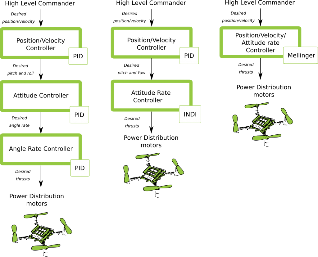
So in order use the thrust of the motors in an useful way to get the Crazyflie to do what you want to do, there are several controllers to consider, which you can see on this quick overview here underneath. It shows the different control paths that can be taken from the high level commander all the way to the power distribution of the motors. Bear in mind that these are still simple representations and that the actual implementation is of course a bit more complicated, but at least it will give you a rough idea of which paths are possible to pursue.
Possible controller pathways
PID Controller
So the default settings in the Crazyflie firmware is the proportional integral derivative (PID) control for all desired state aspects. So the High Level Commander (HLC) will send desired position set-points to the PID position controller (which used to be done off-board, so outside of the Crazyflie firmware before this blogpost). These result in desired pitch and roll angles, which are sent directly to the attitude PID controller. These determine the desired angle rates which is send to the angle rate controller (which is… you guessed… also a PID controller). This is also called Cascaded PID controller. That results in the desired thrusts for the roll pitch yaw and height that will be handled by the power distribution by the motors. (Note that height is mostly handled by the position controller)
INDI Controller
So the Incremental Nonlinear Dynamic Inversion (INDI) controller is an controller that immediately deal with the angle rates to determine the trust. This is a very new addition to the Crazyflie firmware by one of our community members and is based on the implementation of this paper. Currently, the position control is still handled by the same PID controller mentioned in the last paragraph, Nevertheless for handling the angles, it should be faster than the attitude and rate PID controller combined. We have not yet fully tested this out but if you do, let us know how you like it on the Bitcraze forum!
Mellinger Controller
As part of the Crazyswarm project, the controller designed by Daniel Mellinger has been implemented in the Crazyflie firmware as well. Please see this paper about the details of the Mellinger controller. It is a sort of “all in one”: based on the desired position and velocity vectors towards those position, it will calculate right away what the desired thrusts are that need to be distributed to all the motors. This results in a much smoother controlled trajectory of the high level commander and therefore advised to use when the Crazyflie has a precise position estimate (lighthouse and mocap). However, as it is so aggressive, any position estimate of a lesser quality (flowdeck or LPS) will not be sufficient for this controller. See some examples of mellinger controlled flights here and here.
Let us know what you think!
So do you have experience working with these controllers or want to know more about them, please drop us a message on the forum! We are currently working on stabilization and documentation of multiple aspects of the Crazyflie and the controllers is one of them, so we are really interested what your experiences are!
When there is a possibility to name a release with only two’s and zero’s one has to take that opportunity right! Adding to that, it was about time to make a new release, and there is actually another reason. As we wrote about in the “What’s up 2020” blog post, it’s time to look back, finish up and make things more stable. This includes improving documentation, more examples/tutorials etc. With this release we create a good baseline to start this work from.
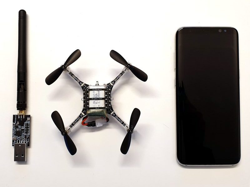
The Crazyflie supports wireless communication using both the Crazyradio PA and BLE (Bluetooth Low Energy https://en.wikipedia.org/wiki/Bluetooth_Low_Energy). BLE is used with the mobile phone apps while Crazyradio PA usually is used together with a PC.
The lower levels of the radio communication in the Crazyflie is handled by the nRF51 that is capable of handling both types of communication. When using the Crazyradio we are using the manufacturers, Nordic Semiconductor, proprietary Enhances ShockBurst protocol (ESB) which makes it simple to send packages, up to 32 bytes, between each other. When communicating over BLE we are using Nordic Semis S110 SoftDevice which is a BLE stack developed by Nordic Semi to simplify implementation.
When we designed the first Crazyflie, the Crazyflie 1.0/Nano, we choose to use the nRF24L01+ that uses the ESB protocol because of simplicity, good range and low latency. Then came the Crazyflie 2.0 and we wanted BLE for mobile client support. Luckily Nordic released the nRF51 which could handle both. However there is a small drawback, both protocols can’t run concurrently and has to be interleaved. For BLE this has never been any problem as this protocol has the priority, but for ESB it means that when BLE is running there will be a small amount of packet loss.
The CRTP protocol we developed that runs on top of the ESB, handles the packet loss fairly well but as more and more Crazyflies are added we have been seeing communication issues. So last week we dived in to this problem and after some digging we understood that BLE was one of the problems. Therefor we added a switch which disables BLE as soon as a ESB packet is received. This improved the ESB connection and it now seems more stable. If you have the possibility we suggest you to get the latest from the crazyflie2-nrf-firmware master branch, try it out and give us feedback.
This change will hopefully provide more stable communication between the Crazyradio PA and the Crazyflie. From a functionality point of view, most users will not see any difference, but we would like to point out that if you have communicated with your crazyflie using the Crazyradio PA, it will not be possible to connect with a mobile phone until the Crazyflie has been re-booted. Note that a simple radio scan with the python client has the same effect and disables BLE.
We are happy to announce that we have gotten Crazyflie 2 to fly autonomously using the Lighthouse deck and Lighthouse V2 base-stations. This was a very requested features, and while this is not stable and ready to use yet, it is a great milestone toward Lighthouse V2 support.
There exists two incompatible versions of the Lighthouse positioning system. Version 1 was released with the original HTC Vive VR system. In this system base-station are using two rotating laser beam that sweeps the room, one horizontal and one vertical, and an omnidirectional synchronization flash to allow IR light receiver to be located in the room. One limitation of this version is that up to two base-station can be used and no more, this is mainly due to the fact that beam identification is done using a TDMA scheme: base stations switch-on their laser in a dedicated time-slot one after each-other and adding more time slots for more base-stations will greatly reduce the update rate of the system.
Lighthouse V2, was released with the HTC Vive PRO headset and is also used by the Valve Index. The big change is that laser sweeps now carries modulated data and that there is only one rotor with two angled slit instead of the two rotors for V1. The V2 sweep data is described as ‘Sync on beam’ and contains timing information of how long it has been since the synchronization event (ie. when the rotor crossed 0 degree). The sweep data also allows to identify the base-station that has transmitted the sweep. This removes the need for an omni-directional synchronization pulse and allows more than two base-station to operate at the same time in the same space, since their sweeps can now be identified and timed.
The lighthouse V2 system is very elegant and scalable. However, actually decoding the signal from the sweeps has taken a lot of time since it is not documented and we needed to find-out what the encoding actually was. There has been effort on the internet to understand how the system worked, the most useful one is this github ticket that goes from raw data acquisition to fully unlocking the beam encoding.
I have been working on-and-off for a long time on making an FPGA design for the lighthouse deck to acquire and decode Lighthouse V2. The main blocking point until now was that I had not been able to reliably acquire useful signal from the system in order to allow real-time decoding on the Crazyflie. Added to that, there was some inconsistency between what we though the system was doing and what we could gather from the base-stations debug console. Recently though, the last piece of the puzzle, was to discover that the beam encoding was not Manchester, as we though, but Bi-phase mark code FM1 (BMC). Once this decoding was used everything made sense and worked.
Added to that, I started using SpinalHDL instead of raw Verilog to write the FPGA design which allows for much quicker iteration, much less frustration, and it also allowed me to easily make the design multi-clock which is required to decode the BMC signal: the beam decoder runs at 48MHz, and the rest of the system works at 24MHz. This design is required since the FPGA we use in the lighthouse deck is not fast enough to run everything at 48MHz.
The result, is a new FPGA firmware for the lighthouse deck that receives, identify and decode Lighthouse V2 sweep signal and send them over to the Crazyflie. The Crazyflie still has a little pulse packing to do (putting together pulses from a single sweep received on multiple sensors) and then can use pulse timing information to calculate azimuth and elevation at which the base-station sees the Crazyflie. This information is the same as the one we get from Lighthouse V1 and so the same algorithm can be used to calculate the Crazyflie position.
I hacked a proof of concept was this last fun Friday and it flies!
If anyone is curious the code for this demo has been uploaded as an out-of-tree driver and the code for the FPGA parts is already in the lighthouse-fpga project. The current Crazyflie code is too incomplete to be usable, but it is a nice starting point if anyone wants to play with Lighthouse V2 and the Crazyflie right away ;-).
As a side note, the Bitcraze team will shrink temporary as I, Arnaud, will go in parental leave until mid-August. I look forward to this new adventure and I trust the lighthouse V2 development and the forum will be in good hands in my absence.
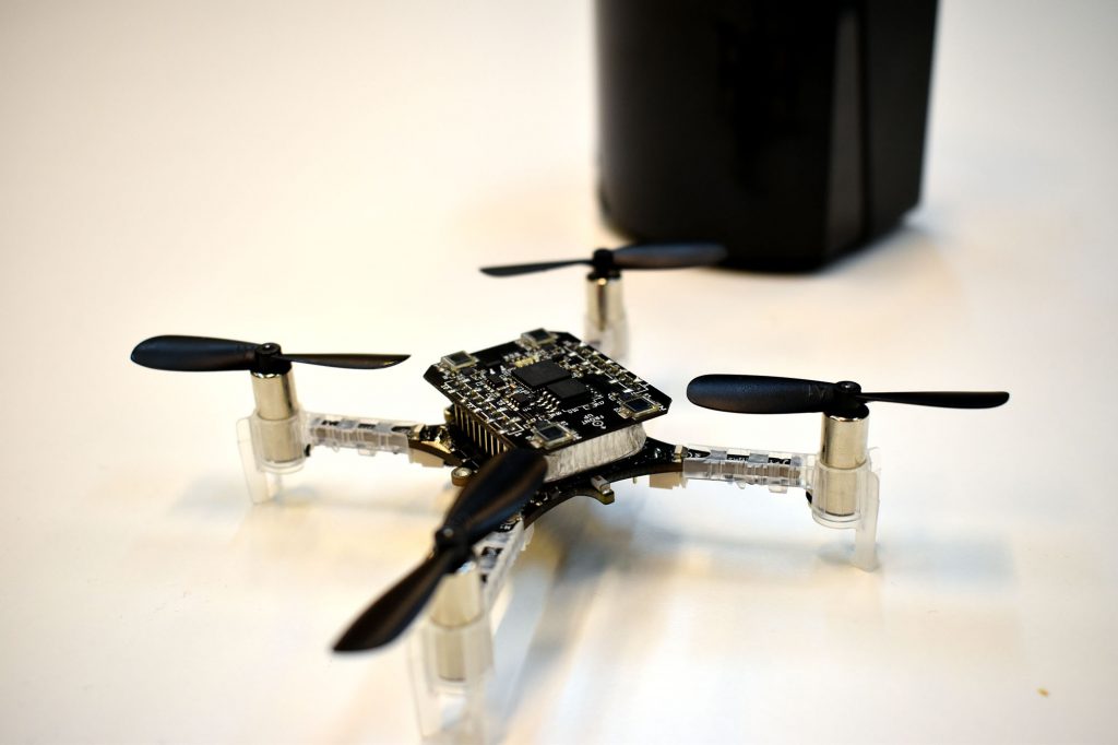
There has been some work done earlier to use the Crazyflie for generating images, for instance the dot-drawing by Paul Kry and light painting. I wanted to see if it is possible to put a brush or pen on a Crazyflie and use it to draw lines on a paper. I decided to use a fun Friday to try it out. The idea is simple: mount a pen on the Crazyflie, put a paper on a wall, write a script to draw a figure, fly!
The setup
The first thing I looked into was to investigate if a Crazyflie can fly with a brush or pen mounted on it. I wanted to keep the weight down and my initial approach was to use a cotton swab (0.6 g) dipped in paint. I found one that was long enough to extend in front of the propellers and I mounted it by squeezing it between the battery and the PCB. Flying was no problem with such low extra weight.
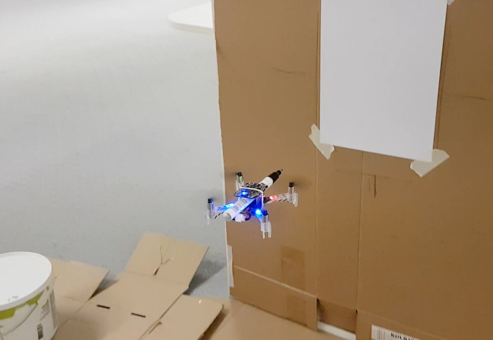
For positioning I decided to use the Lighthouse system. It is very accurate, simple to use and the easiest way to get started. I mounted a piece of cardboard in the YZ-plane of our lighthouse coordinate system, where I could attach a drawing paper. The idea of setting up the drawing surface parallell to the YZ-plane was to make the scripting easier. I (of course) used the Crazyflie and lighthouse system to measure that the cardboard was mounted at the right position.
Finally I wrote a simple python script that utilized the high level commander to move towards the drawing surface and yawing at the right position to draw a stroke on the paper. It sort of worked, but the cotton swab has to be “refilled” before each stroke which took a lot of time, and the results were a bit random.
I decided to try out a pen instead. The upside is that it does not require refill, on the other hand it is much heavier which makes the Crazyflie a bit sluggish when flying. I mounted the pen on the top side of the PCB, squeezed under the Lighthouse deck, and moved the battery to under the Crazyflie to distribute the weight.
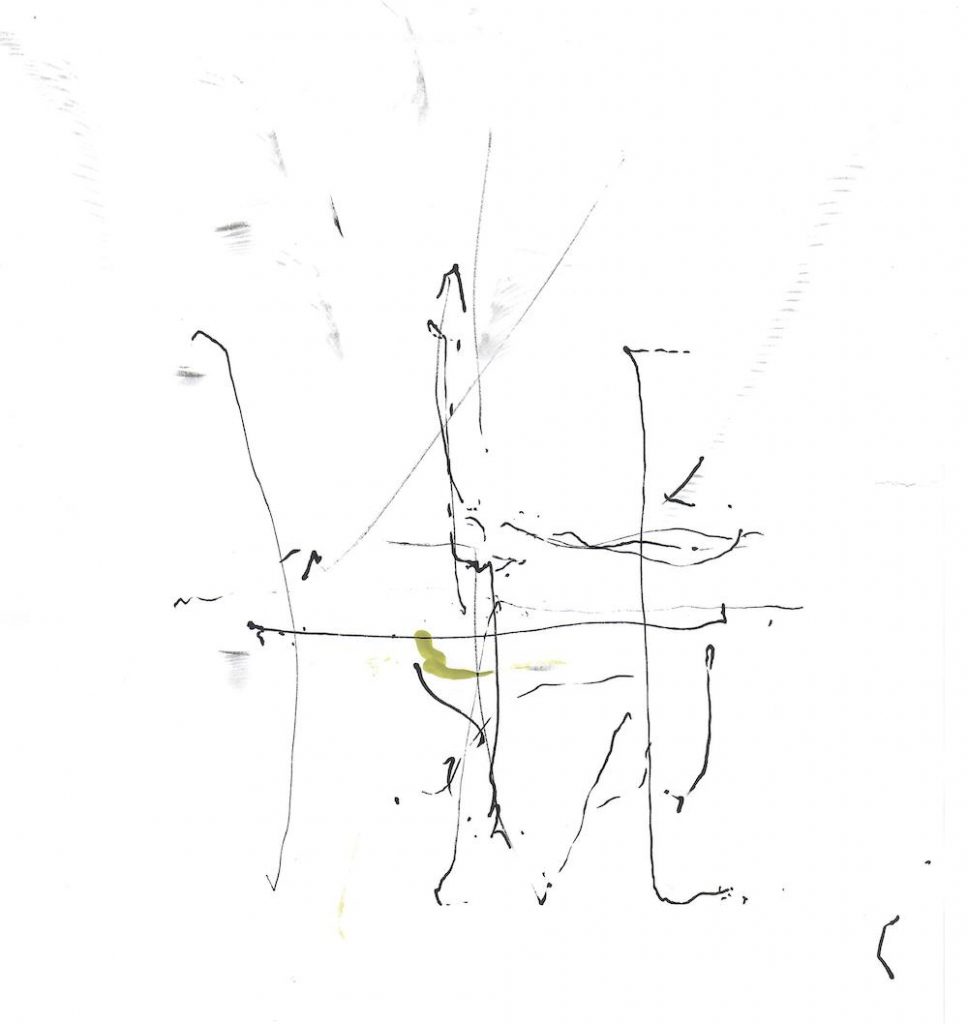
Initial tests – both cotton swab and pen
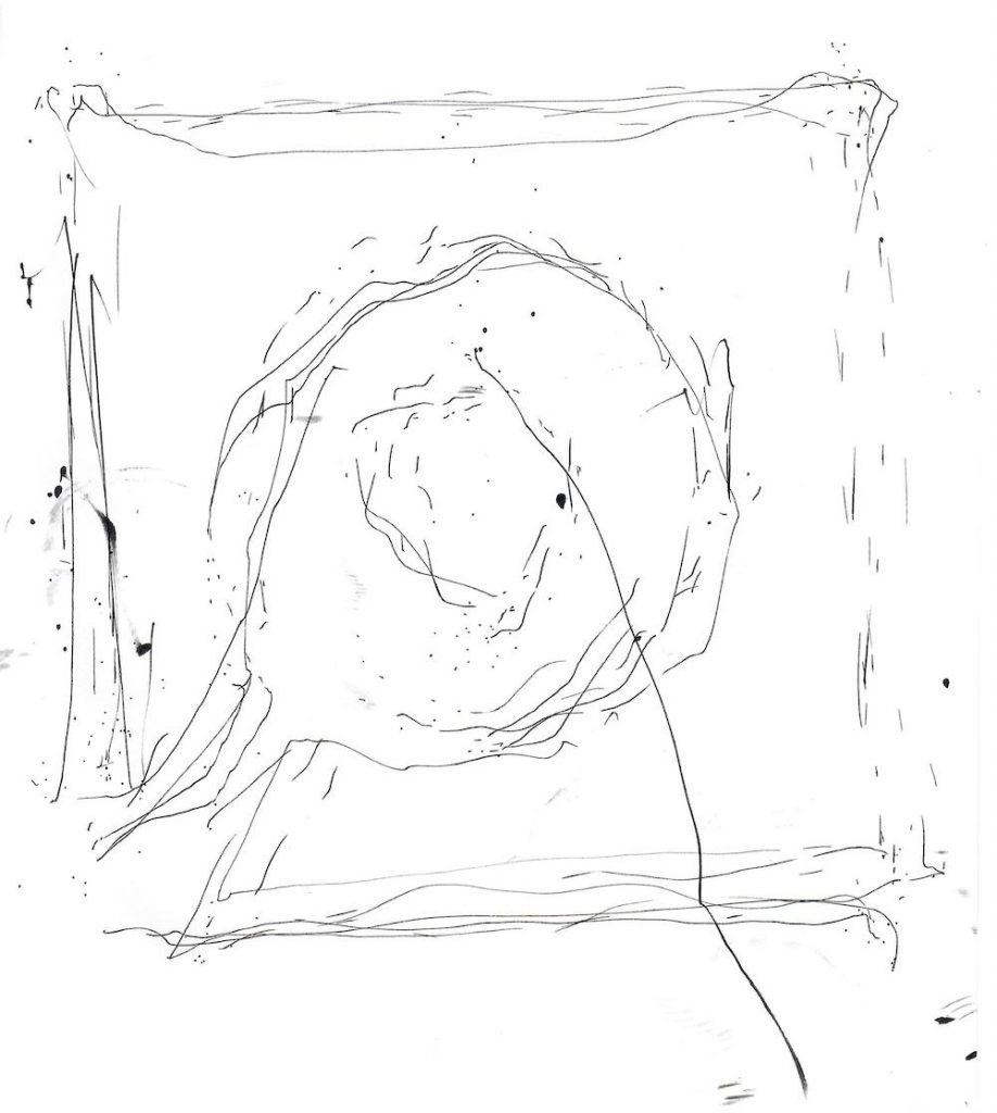
The script was updated to draw the outline of the Bitcraze logo. I had a couple of variations where I tried to draw the full outline in one long stroke, as separate strokes, going up or going down and some other flavours.
So was it successful? Currently the Crazyflie is not a new Picasso, but the painting skills could maybe be improved with some more work. I think the main problems were:
the pen is too heavy and requires too much force on the paper
the controller cannot handle the situation in a good way. In essence I set the set point a few millimeters “into” the paper to push the pen against the surface which seems to be confusing as the controller can not reach the set point.
Flying that close to the drawing surface creates an air flow that disturbs the flight.