The Crazyflie 2.0 was released almost 4 years ago now. When we released it we wanted to avoid limiting our users in hardware. We over-designed it with lots of features and power we weren’t using at the time of release. We also put in the deck connector so we could keep users updated with new hardware without having to replace their Crazyflies.
Over the years there’s been thousands of users and lots of feedback on the product. Most of it great, but there’s of course also been issues that needed to be addressed. The original design concept is still working with new decks coming out and still free CPU cycles, flash and RAM. So instead of major updates we decided to focus on fixing the issues we’ve seen while keeping backwards compatibility for our users.
So today we’re really excited to announce we’ve released the Crazyflie 2.1! The updated version of the Crazyflie brings improved flight performance, better durability and improved radio stability.
Here’s a list of the updates:
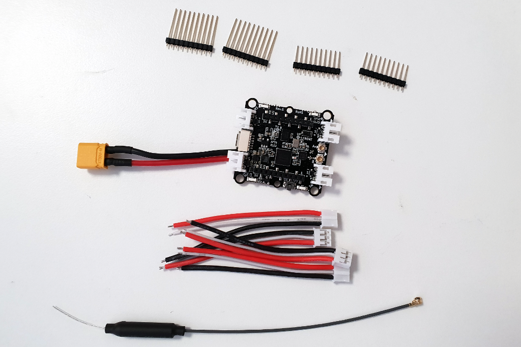
Better radio performance and external antenna support: With a new radio power amplifier we’ve improved the link quality and added support for dual antennas (on-board chip antenna and external antenna via u.FL connector)
Better power button: We’ve gotten feedback that the power button breaks too easily, so now we’ve replaced with a more sturdy alternative.
Improved battery cable fastening: To avoid weakening of the cables over time they now run through a cable relief.
Improved sensors: To make the flight performance better we’ve upgrade the IMU and pressure sensor. The new Crazyflie uses the drone specialized sensor combo BMI088 and BMP388 by Bosch Sensortech. It lowers drift and avoids accelerometer saturation which makes the IMU more “trustable”.
It’s important to note that the Crazyflie 2.1 is a drop-in replacement for the Crazyflie 2.0. All spare parts and decks are compatible with both the Crazyflie 2.0 and the 2.1.
We even took it so far that the same binary can be flashed on the Crazyflie 2.0 and 2.1 without any special care. The binary will automatically activate the right drivers which means working with mixed groups of 2.0 and 2.1 isn’t a hassle.
When releasing the Crazyflie 2.1 we’ve also updated all the bundles to contain the new version. But even though you can’t get the bundles with the Crazyflie 2.0, there’s still some Crazyflie 2.0 units left from the last batch that can be purchased in the E-store.
This week we have a guest blog post from Javier Burgués. Enjoy!
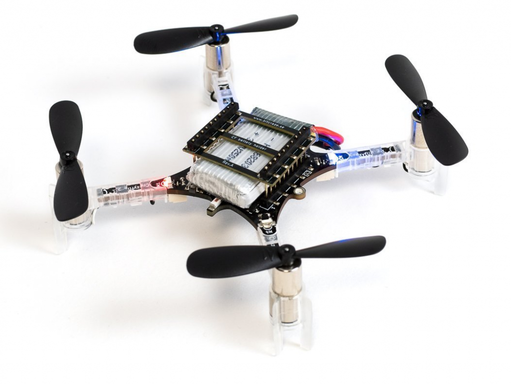
I would like to introduce you a rather unknown application of the CrazyFlie 2.0 (CF2): chemical sensing. Due to its small form-factor, the CF2 is an ideal platform for carrying out gas sensing missions in hazardous environments inaccessible to terrestrial robots and bigger drones. For example, searching for victims and hazardous gas leaks inside pockets that form within the wreckage of collapsed buildings in the aftermath of an earthquake or explosion.
To evaluate the suitability of the CF2 for these tasks, I developed a custom deck, named the MOX deck, to interface two metal oxide semiconductor (MOX) gas sensors to the CF2. Then, I performed experiments in a large indoor environment (160 m2) with a gas source placed in challenging positions for the drone, for example hidden in the ceiling of the room or inside a power outlet box. From the measurements collected in motion (i.e. without stopping) along a predefined 3D sweeping path that takes around 3 minutes, the CF2 builds a map of the gas distribution and identifies the most likely source location with high accuracy.
1. MOX deck
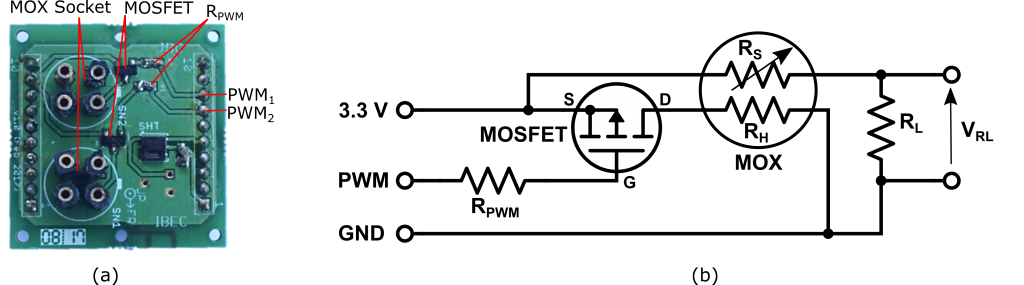
The MOX deck (Fig. 1a) contains two sockets for 4-pin Taguchi-type (TGS) gas sensors, a temperature/humidity sensor (SHT25, Sensirion AG), a dual-channel digital potentiometer (AD5242BRUZ1M, Analog Devices, and two MOSFET p-type transistors (NX2301P, NEXPERIA). I used TGS 8100 sensors (Figaro Engineering) due to its compatibility with 3.0 V logic, power consumption of only 15 mW (the lowest in the market as of June 2016) and miniaturized form factor (MEMS). Since the sensor heater uses 1.8V, two transistors (one per sensor) reduce the applied power by means of pulse width modulation (PWM). The MOX read-out circuit (Fig. 1b) is a voltage divider connected to the μC’s analog-to-digital converter (ADC). The voltage divider is powered at 3.0 V and the load resistor (RL) can be set dynamically by the potentiometer (from 60 Ω to 1 MΩ in steps of 3.9 kΩ). Dynamic configuration of the load resistor is important in MOX gas sensors due to the large dynamic range of the sensor resistance (several orders of magnitude) when exposed to different gas concentrations. The sensors were calibrated (by exposing them to several known concentrations) to convert the raw output into parts-per-million (ppm) concentration units.
Figure 1. (a) MOX deck (without gas sensors); (b) Schematic of the conditioning electronics for each MOX sensor.
The initialization task of the deck driver configures the PWM, initializes the SHT25 sensor, sets the wiper position of both channels of the potentiometer and adds the MOX readout registers to the list of variables that are continuously logged and transmitted to the base station. The main task of the deck driver reads the MOX sensor output voltage and the temperature/humidity values from the SHT25 and sends them to the ground station at 10 Hz.
2. Experimental Arena, External Localization System and Gas Source
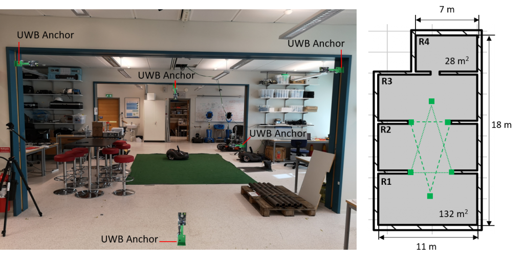
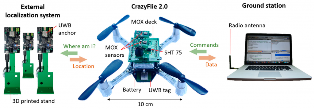
Experiments were performed in a large robotics laboratory (160 m2 × 2.7 m height) at Örebro University (Sweden). The laboratory is divided into three connected areas (R1–R3) of 132 m2 and a contiguous room (R4) of 28 m2 (Fig. 2). To obtain the 3D position of the drone, I used the Loco positioning system (LPS) from Bitcraze, based on ultra-wide band (UWB) radio transmitters. Six LPS anchors were positioned in known locations of the experimental arena and one LPS tag was fixed to the drone. The six LPS anchors were placed in the central area of the laboratory, shaped in two inverted triangles (below and above the flight area).
Figure 2. Experimental arena. The green squares indicate the position of the UWB anchors, which are positioned along two inverted triangles (green lines).
Figure 3. The CrazyFlie 2.0 equipped with the MOX deck and the UWB tag (center) gets its 3D position from the LPS system (left). The location and sensor data are communicated to the ground station (right) over the 2.4 GHz ISM band.
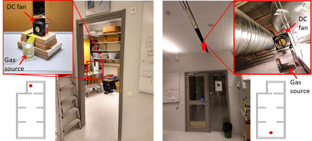
A gas leak was emulated by placing a small beaker filled with 200 mL of ethanol 96% in different locations of the arena (Fig. 4). Ethanol was used because it is non-toxic and easily detectable by MOX sensors. Two experiments were carried out to check the viability of the proposed system for gas source localization and mapping in complex environments. In the first experiment, the gas source was placed on top of a table (height = 1 m) in the small room (R4). In the second experiment, the source was placed inside the suspended ceiling (height = 2.7 m) near the entrance to the lab (R1). Since the piping system of the lab runs through the suspended ceiling, the gas source could represent a leak in one of the pipes. A 12 V DC fan (Model: AD0612HB-A70GL, ADDA Corp., Taiwan) was placed behind the beaker to facilitate dispersion of the chemicals in the environment, creating a plume. The experiments started five minutes after setting up the source and turning on the DC fan.
Figure 4. Gas source location in two experiments. (left) Experiment 1: inside small room; (right) Experiment 2: hidden in suspended ceiling.
3. Navigation strategy
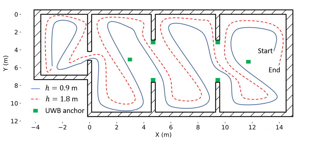
The drone was sent to fly along a predefined sweeping path consisting of two 2D rectangular sweepings at different heights (0.9 m and 1.8 m), collecting measurements in motion (Fig. 5). These two heights divide the vertical space of the lab in three parts of equal size. Flying first at a lower altitude minimizes the impact of the propellers’ downwash in the gas distribution. For safety reasons, the trajectory was designed to ensure enough clearance around obstacles and walls, and people working inside the laboratory were told to remain in their seats during the experiments. The ground station communicates the flight path to the drone as a sequence of (x,y,z) waypoints, with a target flight speed of 1.0 m/s. The CF2 reports the measured concentration and its location to the ground station every 100 ms.
Figure 5. Predefined navigation strategy based on zig-zag sweeping at two heights (0.9 and 1.8 m).
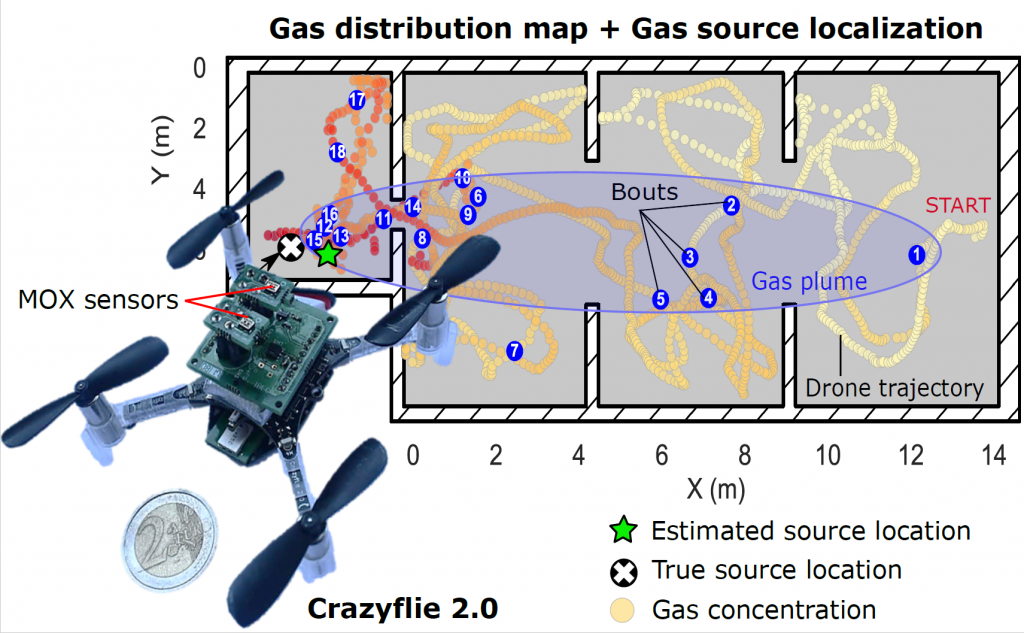
At the end of the exploration, the ground station uses all the received information to compute a 3D map of the instantaneous concentration and the ’bouts’. A ’bout’ is declared when the derivative of the sensor response exceeds a certain threshold. Bouts are produced by contact with individual gas patches and some authors use them instead of the instantaneous response (which is more affected by the slow response time of chemical sensors). For gas source localization, we compare two approaches: using the cell with maximum value in the concentration map or using the cell with maximum bout frequency. The bout frequency (bouts/min) is computed as the bout count in a 5 second sliding window multiplied by 12 (to convert it to bouts/min).
4. Results
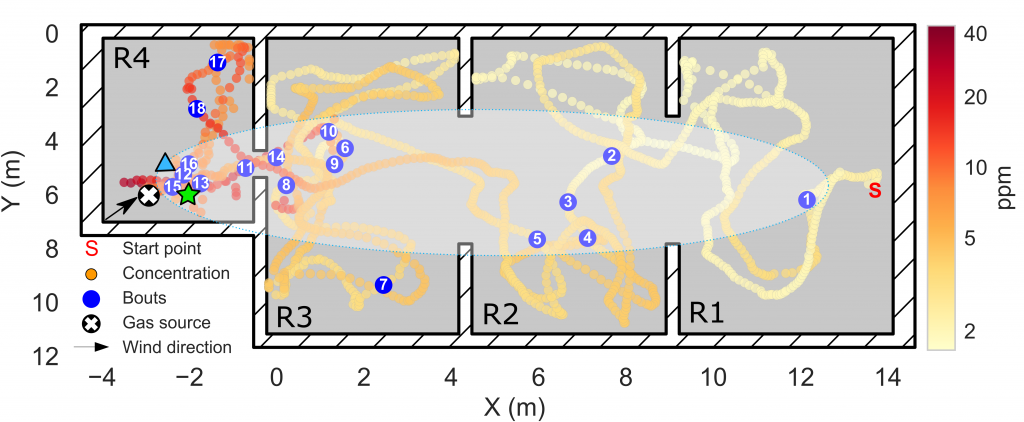
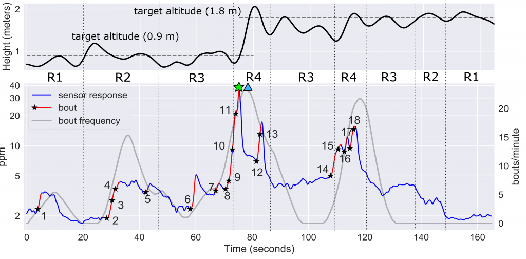
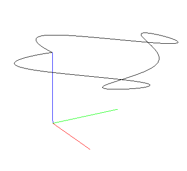
In the first experiment, the drone took off near the entrance of the lab (R1), 17 meters downwind of a gas source located in the other end of the laboratory (R4). From the gas distribution map (Fig. 6a) it is evident that the gas source must be in R4, because the maximum concentration (35 ppm) was found there while concentrations below 5 ppm were measured in the rest of the lab. The gas plume can be outlined from the location of odor hits. The highest odor hit density (25 hits/min) was found also in R4. The cells corresponding to the maximum concentration (green start) and maximum odor hit frequency (blue triangle) were found at 0.94 and 1.16 m of the true source location, respectively.
Figure 6a. 2D map of the instantaneous concentration (ppm) measured in Experiment 1 (in log scale). The odor hits are represented by blue circles. A hand-drawn ellipse outlines the approximate plume shape based on the location of odor hits.
Figure 6b. (top) Trajectory of the CF2 along the z-axis. (bottom) Temporal evolution of the measured concentration (ppm) on a log scale, with odor hits highlighted in red (the black star indicates the start of an odor hit). The identifiers R1–R4 indicate the area of the map in which the drone is flying at each moment. The maximum instantaneous concentration and the maximum odor hit frequency are indicated by a green star and a blue triangle, respectively.
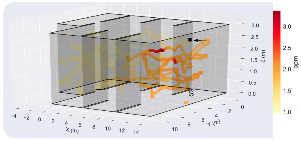
In the second experiment, the gas source was located just above the starting point of the exploration, hidden in the suspended ceiling (Fig. 7). The resulting maximum concentration in the test room was measured when the drone flew at h=1.8 m, highlighting the importance of sampling in 3D for localization and mapping of elevated gas sources. However, since the source is presumably not directly exposed to the environment, concentrations below 3 ppm were found in most locations of the room, which complicates the gas source localization task. The concentration and odor hit maps suggest that the gas source is located in the division between R1 and R2, which represents a localization error of 4.0 and 3.31 m, respectively.
Figure 7. 3D map of the instantaneous concentration (ppm) in Experiment 2. The black square indicates the gas source location (x,y,z) = (14.0, 5.2, 2.7) m, the black arrow the wind direction (positive x-axis) and the letter ‘S’ the starting point of the drone (x,y,z) = (13.5, 5.2, 0.0) m.
5. Conclusions
These results suggest that the CF2 can be used for gas source localization and mapping in large indoor environments. In contrast to previous works in which long measurement times were taken at predefined or adaptively chosen sampling locations, a rough approximation of such maps can be obtained in very short time with concentration measurements acquired in motion. The obtained gas distribution maps seem coherent with respect to the true source location and wind direction, and not only enable the detection of the source with relatively small localization errors but also provide a rich visual interpretation of the gas distribution.
If you are interested in more details about this work, take a look at the journal paper or drop me an email at <jburgues8 at gmail dot com> or leave a comment on the blog!
The lighthouse deck allows the Crazyflie to estimate its position using the HTC Vive tracking base-station normally used for Virtual Reality. The positioning is done by tracking the timing of rotating infra-red laser beams emitted from the base-stations. This system has the advantages of having a very good precision and of allowing the Crazyflie to acquire its position autonomously: once the Crazyflie knows the position and orientation of the base-station, it can calculate its own position without the help of any external systems.
The release as Early Access means that we have finished the hardware and we are confident that the hardware is working properly. Though we have not yet finished all the software and firmware, by releasing the hardware early we can get the hardware into the hands of users quickly to try it out. In return we hope we can get some help making the software better.
Current state
The Crazyflie can calculate its position from the received Vive Base-Station V1 signals.
Direct line of sight should be kept to both base-stations. The Lighthouse deck has 4 receivers so in the future it will be possible to get a position from seeing only one base station.
Base-Station V2 support is still being worked-on, it will only require a software update.
The Base-station position is hard-coded in the Crazyflie and found using SteamVR. Ideally this should be sent from the ground and the Crazyflie should calculate the positions of the Base-Stations automatically.
The previous point means that a full VR system or at least two base stations and a controller or tracker is required to setup the system. In the future we hope to setup the system with only a Crazyflie and two base stations.
Since this version of the deck only has horizontal sensors, it is important that the base-stations are placed above the flight space and the Crazyflies should fly ~40cm bellow the base-stations
As long as the deck is in early access, the main documentation will be the lighthouse positioning page in the wiki. This page is going to be updated a lot in the near future and will track the progress in development.
Demo
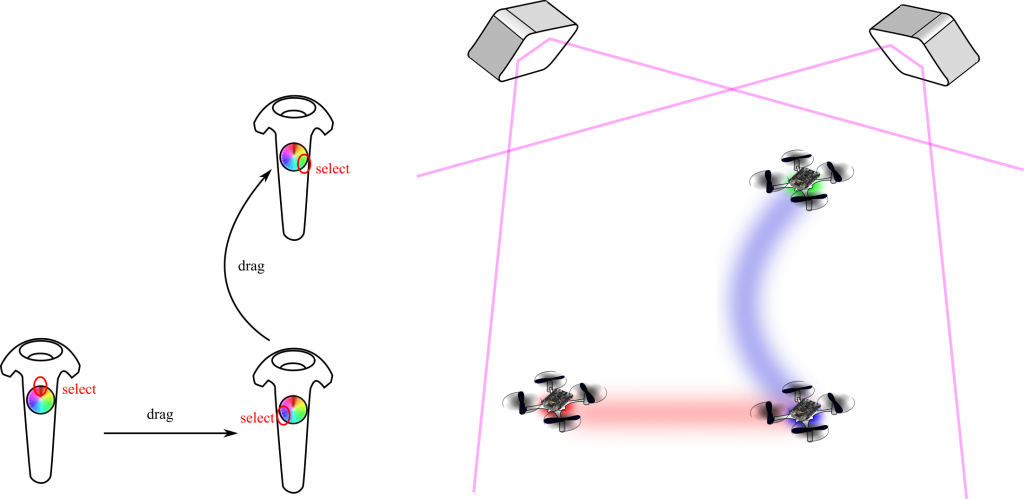
We have written a small demo script that allows to set the position of the Crazyflie using a Vive controller. It is a good demo to experiment with the precision of the system and the ability to mix VR and Crazyflie since they are in the same tracking space:
In this demo, a python script connects to two Crazyflies and acquire the controller position using OpenVR and makes the Crazyflies take-off above the controller. Then, when the controller trigger is pushed, the setpoint to the closest Crazyflie is changed to follow the controller movement, the Crazyflies are flying autonomously only getting position setpoints from the python script. The position estimation and control is handled onboard.
We are pretty excited by this release since we think this positioning technology will be very useful for a lot of use-case. Let us know what you think and do not hesitate to contribute if you want to improve the system :).
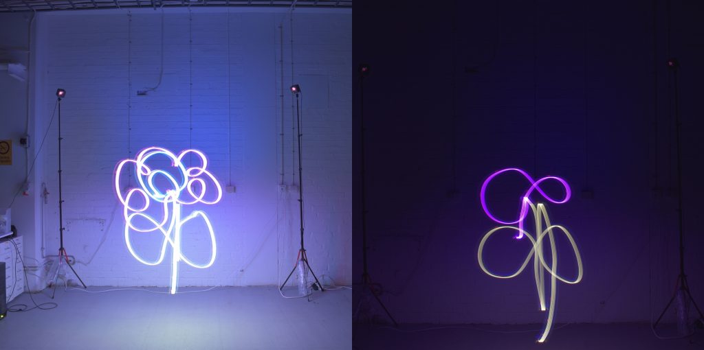
Last week we blogged about the early release version of the lighthouse deck and showed a nice push-around demo of the Crazyflies using the Vive controller. Now we wanted to push the system even further, by making a Lighthouse Painting!
We started by adding a LED-ring deck on the bottom of the CrazyFlie 2.1 with the lighthouse deck attached to the top. We were able to access the input of the track pad of the Vive controller and link it to a specific color / hue value. The LED ring can display any color possible in the RGB range, so in theory, you could paint in whatever color you like. For now, the brightness was fixed, but this could be easily added to the demo script as well.
To capture the light trace, we needed to make a long-exposure image, therefore, the flight arena need to stay completely dark. Luckily, this was easy to do for us since we do not have any windows in our new testing arena. Our camera is the Canon D5600 with a manually controlled shutter time setting selected (press to open the shutter and press again to close the shutter). The aperture setting was set at F-22. Nevertheless, this is very depended on the environment, so we had to do some trial-and-error in order to get this parameter right.
Aperture too wide… perfect!
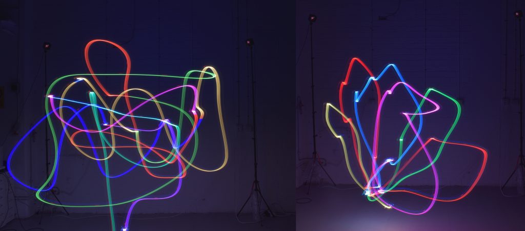
Once we had the set-up finished, we made several long exposure photo paintings with one person controlling the camera and another painting the picture into thin air. Of course, the artist would need to imagine its creation, as we were not able to see the result until after the picture was taken. Also, big gestures were required in order to complete the painting, as the Crazyflie’s and the Vive controller’s movements were synced 1:1, so adding some multiplication factor would come in handy. Nonetheless, the results were amazing.
Some nice examples of a single crazyflie flying based on the Vive’s position, changing color based on the trackpad
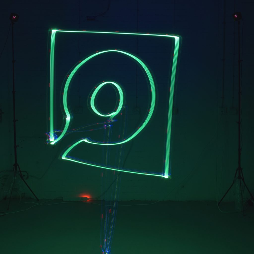
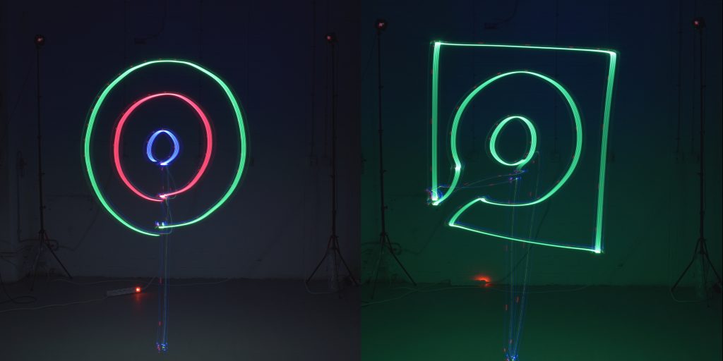
We took it even further, by making the Crazyflie fly a predefined trajectory and planned color scheme without the Vive controller. First, it flew three concentric circles in green, red and blue with the high level commander with the PID controller setting. But, the circles would probably be closed-off more properly with the Mellinger controller setting. We also were able to reproduce the Bitcraze logo in the same fashion. In both long-exposure photos, it still possible to see the Crazyflie, as it is still traceable due to its routine LED functionality, so you can easily observe where it took off, and where it flew in between shapes.
The Crazyflie flying a predefined trajectory in several shapes
The demo python scripts of the above flights can be found here:
An we also took a video of the Bitcraze logo being drawn. The mobile phone camera had some problems focusing in the dark, but it gives a good idea of how things works:
Last week we posted about painting with the Lighthouse deck. This week we continue on the same track but add a new dimension, all in our “let’s try this crazy idea” spirit. So last Friday, after having a lot of fun painting with the Crazyflie led-ring using long exposure photo and the Lightouse deck for positioning, we had one extra crazy idea. Can we use the Crazyflie to show a raster image, very much like the way a CRT monitor works by sweeping line by line and displaying the pixel color one by one, using the led-ring? Unfortunate we did not have enough time that day…
However the idea was so intriguing that Kristoffer couldn’t stop himself from writing a prototype script during the week-end. So last Monday, just after publishing the blog post, we went to the flight arena and tried it. After a couple of trial and error we found a display algorithm that showed a pretty good result:
Crazy-Lisa
The source for this image is this very low resolution Mona Lisa:
It was a very fun experiment, it is magic to see the Crazyflie going back and forth blinking for ~3 minutes, click on the camera and see the resulting picture. It is also a really nice way to observe the current state of the lighthouse positioning. The lines are spaced by about 3 cm and the Crazyflie is controlled using the PID controller. The controller do a decent job of keeping the Crazyflie in lines and the space seems a little bit ’tilted’.
As a side note, we will be exhibiting at the ICRA 2019 conference May 20-24, 2019 in Montreal, Canada. We will running demo of the LPS and Lighthouse (though I am not sure we can print long exposure picture, this is not so exciting to look in real-time :). We hope you would like to come and meet us there!
Today we received a bunch of MoCap marker decks which means they are now available in our shop. This is a handy deck for those that flies in a motion capture system as it is easy to create different configurations and move between Crazyflies.
The deck is designed in collaboration with Qualisys. We suggest using 6.5mm, 8mm or 9.5mm diameter reflective motion capture markers. Currently we don’t offer the markers but soon we will also offer a bundle together with markers.
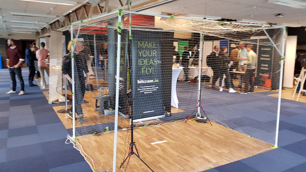
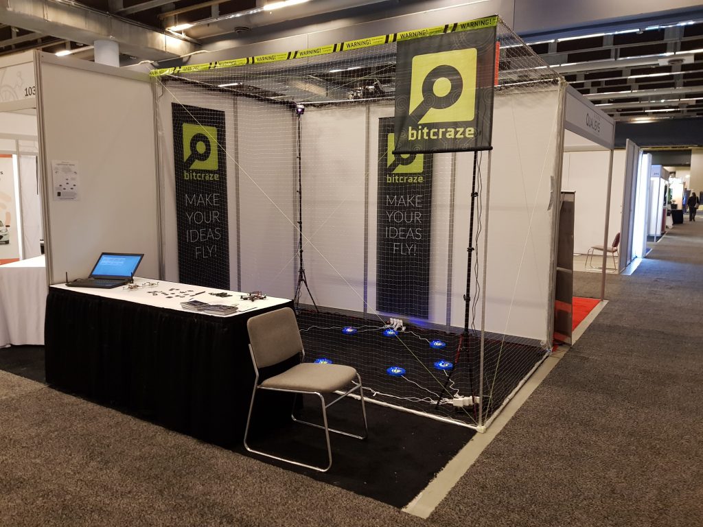
We attended the Innovation Week at Lund University on Thursday last week. Primarily we wanted to talk to students and possibly find future colleagues (yes, we are hiring) but it was also a good opportunity to get some demo time with the Lighthouse positioning system.
The demo setup. A bit blurry, sorry!
As mentioned in an earlier blog post, we are going to ICRA in May and we have started to think about what to demo. The main feature will of course be the Lighthouse deck. The setup at Innovation week also served the purpose of a first iteration for the ICRA setup.
We reused an old cage that we created for another fair a couple of years ago, built from a garden tent. It turned out to be fairly wobbly and a bit heavy (steel tubing) considering we will bring it in our luggage to Canada. We probably have to rethink the construction a bit and see if we can change to aluminium.
We put the Lighthouse base stations on tripods, which worked like a charm in our flight lab. We found that we had a lot of problems calibrating the system, not to mention flying the Crazyflie, at the Innovation week fair though. It turned out that the floor was not as stable as one might expect and that the tripods were swaying when people walked by. We solved the problem by adding a tube to the top of tripod that was pushed against the ceiling and thus minimizing the movement. Experience from the real world is always useful!
The general idea for the demo at ICRA is to automate as much as possible to give us more time with visitors. With the high precision of the Lighthouse system, it should be easy to land the Crazyflies on Qi chargers to avoid changing batteries. We hope to set up 6-8 Crazyflies where one is always flying while the others are charging, and have the possibility to temporarily fly more Crazyflies for small swarms. It is still just ideas and we will not see the end result until we are at ICRA, but it will be fun to build!
As part of our collaboration with Qualisys we are helping them developing an active marker deck for their motion capture cameras. One of the major benefits with an active marker deck is that it can have an ID, thus it is much easier to track each Crazyflie in e.g. a swarm. Another benefit is an increased range compared to passive markers thanks to high power emitting IR LEDs.
Active marker deck mounted on a Crazyflie
We are currently only in the prototype stage but we have already managed to do initial fight tests so hopefully we can release it within a couple of months.
We will bring some prototypes to ICRA 2019, come and visit us and Qualisys to check the deck out.
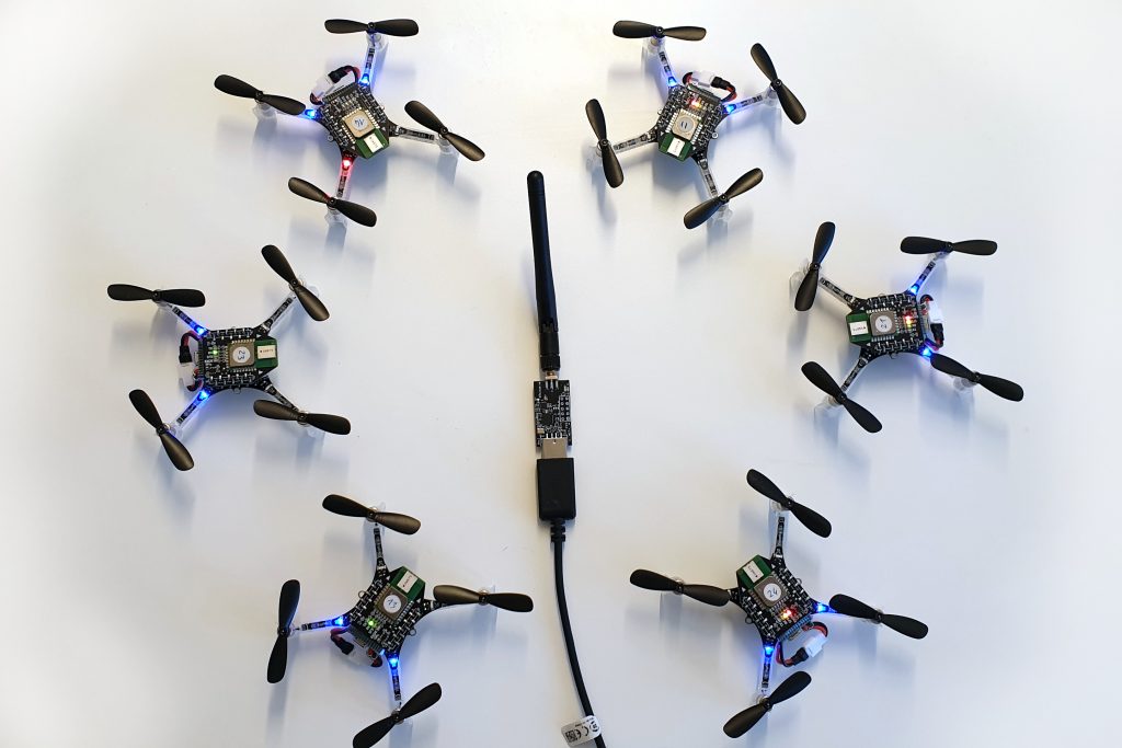
One Crazyflie flying and 5 re-charging on their pads
Running a demo with flying Crazyflies at a conference, usually means a lot of work with changing and charging batteries, starting demos and so on. This takes time and leads to less time to talk to all the interesting people that visit our booth. This year we are aiming at making the demo as fully automated as possible. We will have 8 Crazyflie 2.1 with Lighthouse and Qi charger decks, each with a charging pad. A computer will orchestrate the Crazyflies and make sure one is flying at all times while the others re-charge their batteries. When the battery of the flying Crazyflie is depleted it goes back to its pad while another one takes over.
Most of the functionality is implemented in the Crazyflie firmware and it is pretty much autonomous after the trajectory is started. It will fly the trajectory over and over until it is low on battery, when it goes back to where it started from for recharging. Even though the Lighthouse positioning is very good, it sometimes slips off the charging pad when landing, so we have added a reposition feature to take off again and land if it is not charging after landing.
The orchestration computer (we call it the Control tower) is just keeping track of the state of the flying copter and starts a new one when the flying one goes back the the pad.
We are reusing the spiral trajectory from IROS last year and it has the property that it is possible to run up to 4 copters at the same time without colliding, if they are started at the correct times. There is a swarm feature in the Control tower that runs up to 4 Crazyflies with continuous replacements. The chargers are not fast enough to keep it going and it does not work as expected every time, but it is exciting with a few more Crazyflies buzzing around!
You can find us in booth 101 at ICRA 2019, May 20 – 22. Drop by and say hi, check out the demo and tell us what you are working on. We love to hear about all the interesting projects that are going on. See you there!
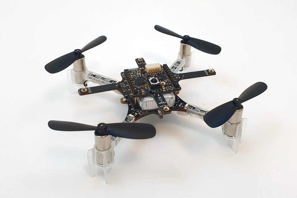
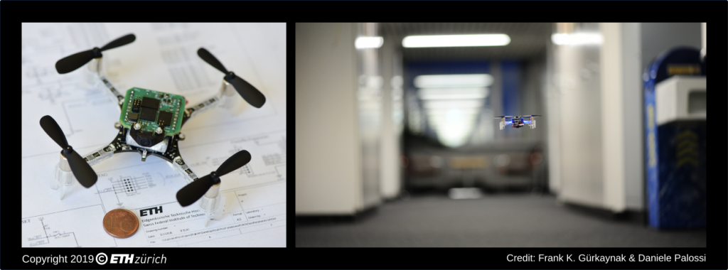
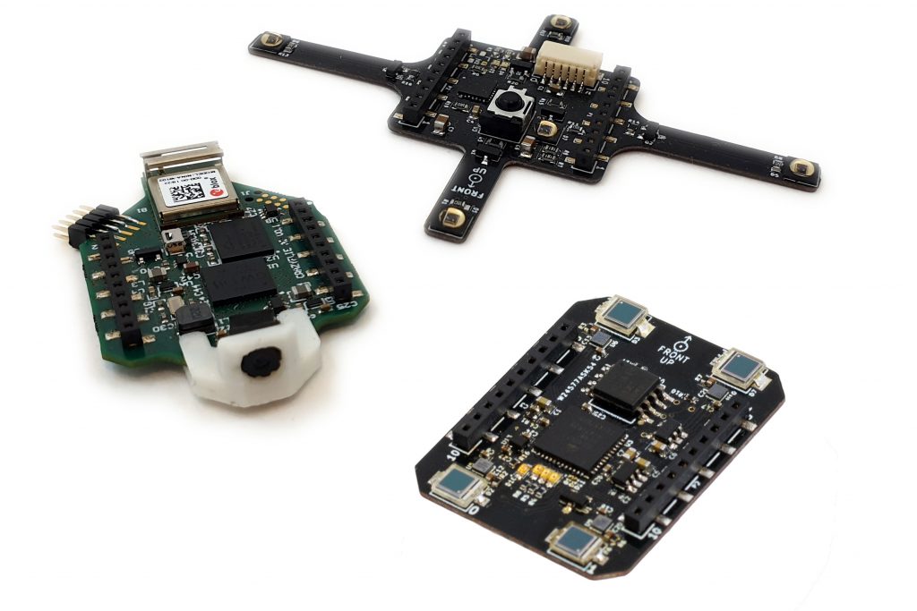
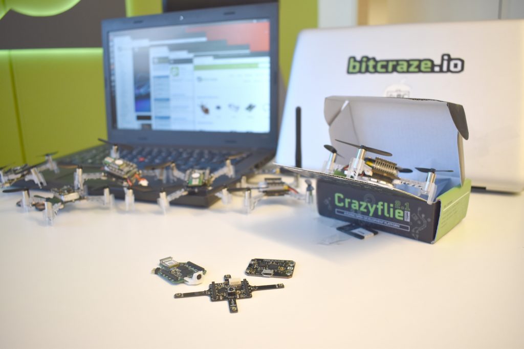
Hi everyone, here at the Integrated and System Laboratory of the ETH Zürich, we have been working on an exciting project: PULP-DroNet. Our vision is to enable artificial intelligence-based autonomous navigation on small size flying robots, like the Crazyflie 2.0 (CF) nano-drone. In this post, we will give you the basic ideas to make the CF able to fly fully autonomously, relying only on onboard computational resources, that means no human operator, no ad-hoc external signals, and no remote base-station! Our prototype can follow a street or a corridor and at the same time avoid collisions with unexpected obstacles even when flying at high speed.
PULP-DroNet is based on the Parallel Ultra Low Power (PULP) project envisioned by the ETH Zürich and the University of Bologna. In the PULP project, we aim to develop an open-source, scalable hardware and software platform to enable energy-efficient complex computation where the available power envelope is of only a few milliwatts, such as advanced Internet-of-Things nodes, smart sensors — and of course, nano-UAVs. In particular, we address the computational demands of applications that require flexible and advanced processing of data streams generated by sensors such as cameras, which is beyond the capabilities of typical microcontrollers. The PULP project has its roots on the RISC-V instruction set architecture, an innovative academic and research open-source architecture alternative to ARM.
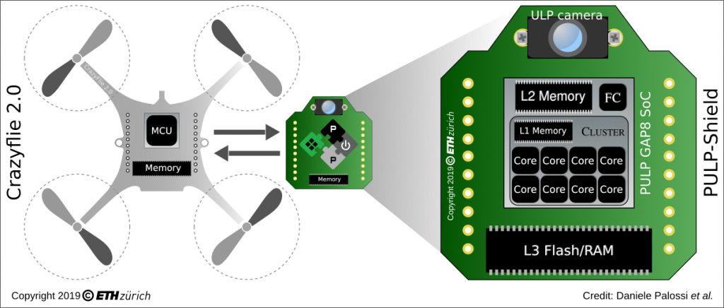
The first step to make the CF autonomous was the design and development of what we called the PULP-Shield, a small form factor pluggable deck for the CF, featuring two off-chip memories (Flash and RAM), a QVGA ultra-low-power grey-scale camera and the PULP GAP8 System-on-Chip (SoC). The GAP8, produced by GreenWaves Technologies, is the first commercially available embodiment of our PULP vision. This SoC features nine general purpose RISC-V-based cores organised in an on-chip microcontroller (1 core, called Fabric Ctrl) and a cluster accelerator of 8 cores, with 64 kB of local L1 memory accessible at high bandwidth from the cluster cores. The SoC also hosts 512kB of L2 memory.
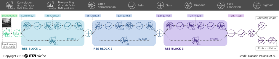
Then, we selected as the algorithmic heart of our autonomous navigation engine an advanced artificial intelligence algorithm based on DroNet, a Convolutional Neural Network (CNN) that was originally developed by our friends at the Robotic and Perception Group (RPG) of the University of Zürich. To enable the execution of DroNet on our resource-constrained system, we developed a complete methodology to map computationally-intense deep neural networks on the PULP-Shield and the GAP8 SoC. The network outputs two pieces of information, a probability of collision and a steering angle that are translated in dynamic information used to control the drone: respectively, forward velocity and angular yaw rate. The layout of the network is the following:
Therefore, our mission was to deploy all the required computation onboard our PULP-Shield mounted on the CF, enabling fully autonomous navigation. To put the problem into perspective, in the original work by the RPG, the DroNet CNN enabled autonomous navigation of big-size drones (e.g., the Bebop Parrot). In the original use case, the computational power and memory was not a problem thanks to the streaming of images to a remote base-station, typically a laptop consuming 30-100 Watt or more. So our mission required running a similar workload within 1/1000 of the original power. To make this work, we combined fixed-point arithmetic (instead of “traditional” floating point), some minimal modification to the original topology, and optimised memory and computation usage. This allowed us to squeeze DroNet in the ultra-small power budget available onboard. Our most energy-efficient configuration delivers 6 frames-per-second (fps) within only 64 mW (including all the electronics on the PULP-Shield), and when we push the PULP platform to its limit, we achieve an impressive 18 fps within just 3.5% of the total CF’s power envelope — the original DroNet was running at 20 fps on an Intel i7.
Do you want to check for yourself? All our hardware and software designs, including our code, schematics, datasets, and trained networks have been released and made available for everyone as open source and open hardware on Github. We look forward to other enthusiasts contributions both in hardware enhancement, as well as software (e.g., smarter networks) to create a great community of people interested in working together on smart nano-drones. Last but not least, the piece of information you all were waiting. Yes, soon Bitcraze will allow you to enjoy of our PULP-shield, actually, even better, you will play with its evolution! Stay tuned as more information about the “code-name” AI-deck will be released in upcoming posts :-).
Only a week left until we stand in our ICRA booth in Montreal and give you a gimps of what we do here at Bitcraze. As we have been writing about earlier we are aiming to run a fully automated demo. We have been fine tuning it over the last couple of days and if something unpredictable doesn’t break it, we think it is going to be very enjoyable. For those that are interested in the juicy details check out this informative ICRA 2019 page, but if you are going to visit, maybe wait a bit so you don’t get spoiled.
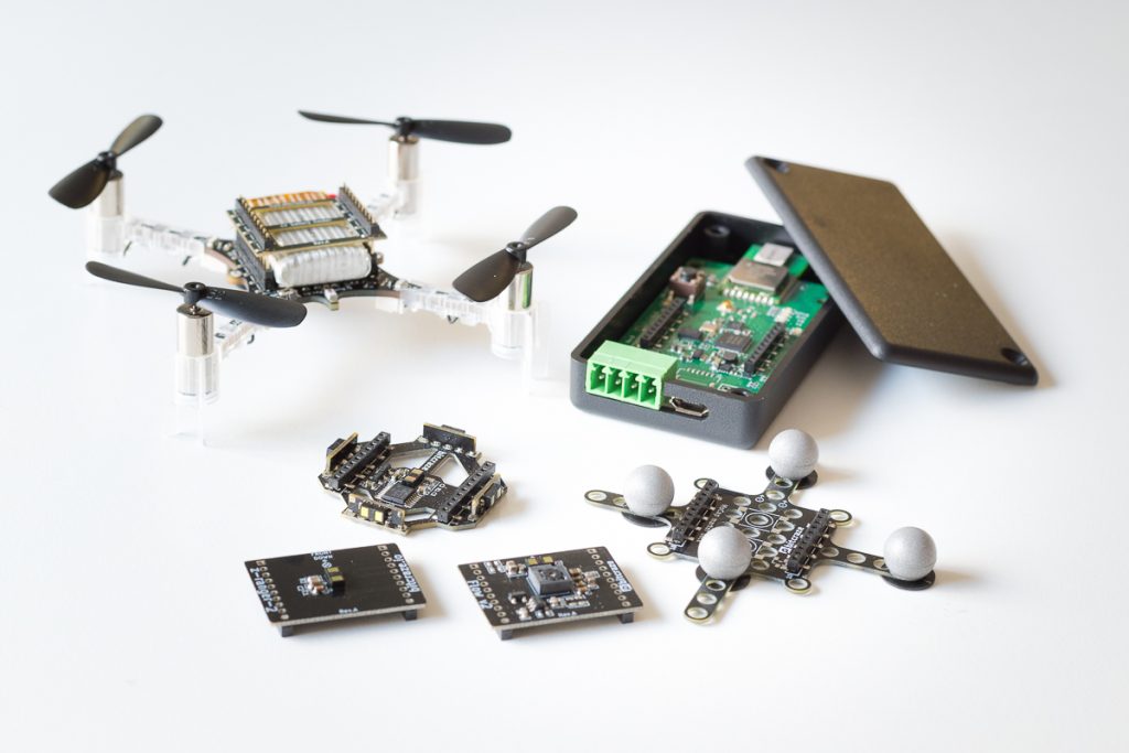
Apart from the demo we are also going to show our products as well as some new things we are working on. The brand new things include:
AI-deck, Active marker deck and Lighthouse-4 deck
AI-deck: This is a collaborative product between GreenWaves Technologies, ETH Zurich and Bitcraze. It is based on the PULP-shield that the Integrated and System Laboratory has designed. You can read more about it in this blog post. The difference with the PULP-shield is that we have added a ESP32, the NINA-W102 module, so that video can be streamed over WiFi. This we hope will ease development and add more use cases.
Active marker deck: Another collaboration, but this time with Qualisys. This will make tracking with their motion capture cameras easier and better. Some more details in this blog post. Qualisys will have the booth just next to us were it will be possible to see it in a live demo!
Lighthouse-4 deck: Using the Vive lighthouse positioning system this deck adds sub-millimeter precision to the Crazyflie. This is the deck used in the demo and could become the star of the show.
Adding to the above we will of course also display our recently released products:
Crazyflie 2.1: The Crazyflie 2.1 is an improvement of the Crazyflie 2.0 but keeping backward capability.
Better radio performance and external antenna support: With a new radio power amplifier we’ve improved the link quality and added support for dual antennas (on-board chip antenna and external antenna via u.FL connector)
Better power button: We’ve gotten feedback that the power button breaks too easily, so now we’ve replaced with a more solid alternative.
Improved battery cable fastening: To avoid weakening of the cables over time they are now run through a cable relief.
Improved sensors: To make the flight performance better we’ve switched out the IMU and pressure sensor. The new Crazyflie uses the drone specialized sensor combo BMI088 and BMP388 by Bosch Sensortech.
Flow deck v2: The Flow deck v2 has been upgraded with the new ST VL53L1x which increases the range up to 4 meters
Z-ranger deck v2: The Z-ranger v2 deck has been upgraded with the new ST VL53L1x which increases the range up to 4 meters
Multi-ranger deck: The Multi-ranger deck adds VL53L1x sensors in all directions for mapping and obstacle avoidance.
MoCap marker deck: The motion capture deck with support for easily attachment of passive markers for motion capture camera tracking.
Roadrunner: The Roadrunner is released as early access and the hardware is basically a Crazyflie 2.1 without motors and up to 12V input power. This enables other robots or system to use the loco positioning system.
You can find us in booth 101 at ICRA 2019 (in Montral, Canada), May 20 – 22. Drop by and say hi, check out the products & demo and tell us what you are working on. We love to hear about all the interesting projects that are going on. See you there!
3 of us where at ICRA 2019 in Montreal last week, where we met a lot of interesting people and a lot of Crazyflie users. Thanks a lot to everyone that drop by our booth, and for the ones that missed it we are planning on being at iROS2019 later this year so we might see you there :-).
We have already described our demo in a previous post, now that we run it we can update on how it went. We are also updating the ICRA2019 page with the latest source code and information so that anyone interested can reproduce the demo.
In its final state at the conference, the demo contained 8 Crazyflies 2.1 equiped with Lighthouse deck and Qi charger deck. There were 8 3D-printed charging pads on the floor with Ikea Qi wireless chargers and two HTC Vive base stations (V1) on tripods. The full system was contained in a cage, built from 50 cm-long tubes or aluminium and nets.
The full setup of the booth took us about 4 hours, this included about 3 hours for the cage, 15 min for the demo including calibration of the lighthouse base-station geometry and the rest to fine-tune things. This is by far our best setup time, we still need to prettify the cage a bit and to make is easier to install, but we will most likely re-use this system for upcoming conferences.
In this demo we aimed at keeping a Crazyflie in the air at every moment, to do so we had a computer connected to all 8 Crazyflies sending to one of them the signal to start flying if no other where actually in the air flying a trajectory. The flight was completly autonomous as we explained in our previous blog post. We setup the Crazyflie to fly 2 cycles and then land, which increase the rate of swap and so increased the ‘action’, though it also meant that during the swap two Crazyflies where flying. This drained the batteries a bit more than expected and meant that after about an hour all the Crazyflies where bellow the take-off threshold and we had to wait ~30 seconds between flights. Here is a video of it in action:
The demo was very care-free, we had very few Crashes and we mostly restarted the Crazyflies to swap batteries manually to add a bit of power in the swarm. The last day we decided to spice it up a little bit by adding a chair in the cage and by calibrating the chair position and flight trajectory, we managed to have the Crazyflie partly fly under it. This worked quite well most of the time and showed that the lighthouse positioning is repeatable and works fairly well with short occlusion in the path. Though we also found out that even though a single Crazyflie would always fly the same trajectory, two different Crazyflies will not. We think differences in propeller stiffness and the fact that the our Mellinger position controller has not been calibrated for changing YAW are the main reasons.
If you want to know more about the demo or if you want to reproduce it do not hesitate to visit the ICRA 2019 page that explains it in more details and links to the source code of everything including 3D printed parts for the cage and the landing pads.
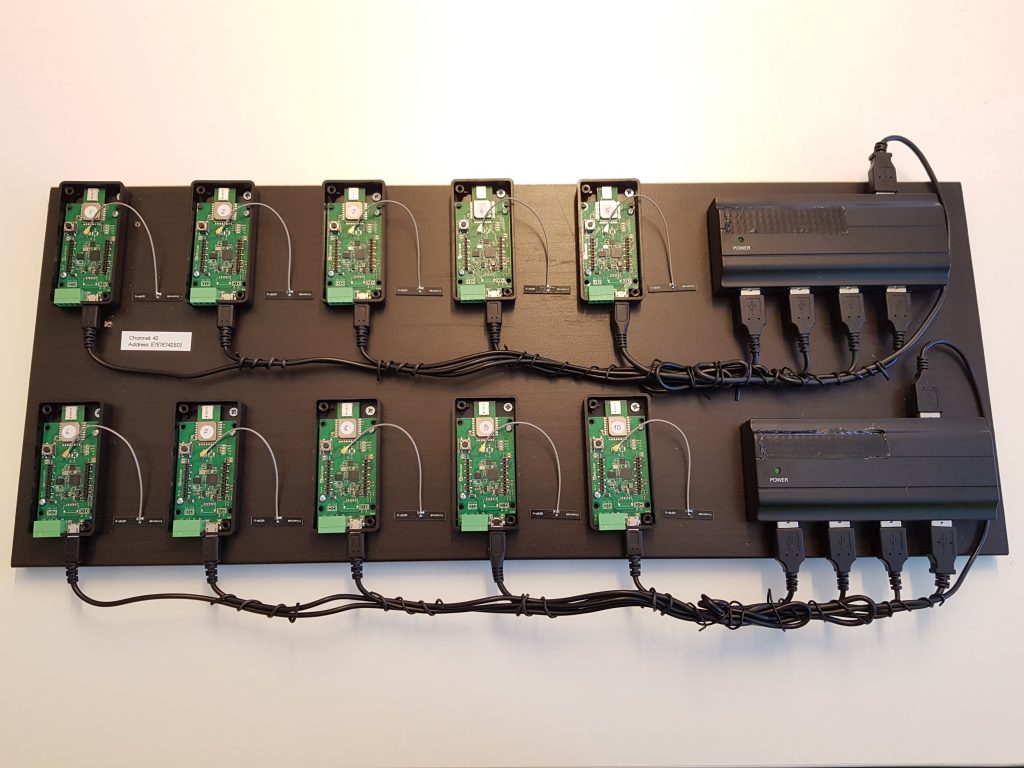
While running our ICRA demo, we came across a bug in the Crazyflie python-lib radio handling, limiting the number of Crazyflie that could be controlled using one Crazyradio PA. Communication with many Crazyflies is crucial as flying swarms is becoming more of an interesting topic for research and education. So we decided to take the problem at hand and create a radio test-bench:
To make the test-bench we have attached 10 roadrunner boards to a plank of wood together with USB switches that can provide enough power to the roadrunners. We used the roadrunner because it is mechanically easier to use in this context and it has an identical architecture to the Crazyflie 2.1 when it comes to the radio implementation.
Initially we will use the test-bench to run test scripts that pushes the communication to its limits and that consistently test the communication stack functionalities. This should allow us to find bug and verify that we solve them as well as discovering and documenting limitations.
Eventually we want to connect a raspberry-pi to the test-bench and run tests for each commit and pull-request to the crazyflie-firmware, crazyflie2-nrf-firmware and crazyflie-lib-python projects. This will guarantee that we do not introduce new limitations in the communication stack. The test-bench will also be very useful in implementing new functionalities like direct crazyflie-to-crazyflie P2P communication.
As a final note, the Crazyswarm project is not affected by the Crazyflie-lib bug since it is using the C++ implemented crazyflie-ros driver. Hence Crazyswarm can control more Crazyflies per Crazyradio PA, so it is still the preferred way to fly a swarm mostly when using a motion capture system. Though, with the progress made on LPS and Lighthouse positioning, running swarms, using the python API directly is a probably a more lightweight alternative.
Many of our users are flying larger and larger swarms and we’ve been getting some feedback that there’s communication issues when connecting to many Crazyflies. So during the last weeks we’ve been looking at this. Among the things we’re doing is building a test rig where we can automate the communication testing (last weeks blog post). We’ve also fixed a few communication issues listed below.
One of the issues causing problems is dropping packages coming in to the Crazyflie. If the flow of packages was too high to one CRTP port these would start dropping. This has now been fixed by increasing the length of the queues for each port. (GitHub issue)
Another issues has been logging data piling up after disconnect. The detection for the radio disconnection was boken so logging data would continue to be generated and pushed into the communication stack. This has now been fixed so logging will be reset which should clear up he congestion on the next connect. (GitHub issue)
Lastly we also fixed the USB communication issue with dropped packages and crashing when the USB was disconnected. (GitHub issue)
We’ve already noticed a few other issues when using the rig so there should be more fixes coming soon. In the meantime test out the new firmware and let us know if there’s still issues.
We have now come to a the point were we will start manufacturing of the Crazyflie Bolt, Formally known as the RZR. You might wonder why we changed the name… Well the RZR more implies it is a Racer quad and it really isn’t. This is mainly because of the design in power distribution which is limited to around 8A per motor. However by using your own PDB it will work well for that too. But that is not the intention, it is more intended to have the strengths of the Crazyflie 2.1 but in a slightly bit bigger package. Therefore we wanted a better name for it and after a brainstorming session we came up with the name, Bolt. Both as it is a Crazyflie building block, a bolt used to fasten things, but also because it has the potential to be fast, as in a lightning bolt. Great name right :-)
The CF-Bolt development has been pushed back many times because of other more promising products, but finally it is getting here. If things goes according to plan, the Crazyflie Bolt should be in our shop in Aug-Sept. If you want to read up on the history and what it is all about read about the first flight to the almost-final prototype here.
A quick recap of the features:
Fully compatible with the CF2 firmware, expansion decks as well as radio.
Connectors to attach motor controllers (also possible to solder though) so it is easy to build and repair.
Power distributions built into controller board. (Max ~8A per motor controller) with XT30 connector.
Motor controllers can be switched off by the system (MOSFET) so the system can go into deep sleep and only consume around 50uA.
Voltage input 1S-4S (3V to 17V).
Standard mounting (M3 mounting holes spaced 30.5mm in a square).
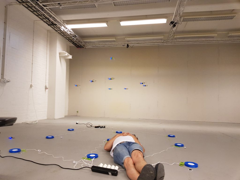
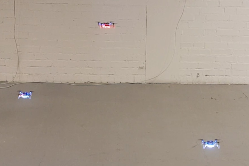
We have recently moved to a new bigger office. With the summer arriving in Sweden, it was time to organize a small move-in after-work party with friends and family. For the occasion we wanted to play around with a small swarm of Crazyflies and the new Lighthouse positioning. Time being a sparse resource, we setup the ICRA2019 demo in the flight lab so that we would be able to fly during the party. We also started looking at our old swarm show that we ran with the LPS a year ago to see if we could run it with Lighthouse:
The show was a essentially a sequence of setpoints sent from a python script and controlling 9 Crazyflies 2.1 equipped with Lighthouse deck on the top and led-ring deck on the bottom synchronized on music. We setup the Crazyflie in the Lighthouse positioning system and converted the script to use the high-level-commander GOTO setpoints. We look forward at trying more advance control problems like trajectories to make more impressive synchronized flight choreography in the future but for now it already look quite good even with only GOTOs:
Summer is here and temperatures are rising. Since many of us will be on holidays, we will focus this quarter on a special summer clean up! See here what we are working on:
Fixing issues: This time we are aiming to close many of the issue tickets in our Github repositories, so that after the summer everything will run much more smoothly (we hope!). Definitely our test rig will come in very hand to sniff out more issues in terms of radio communication as well. You can help as well! Everybody who is using and developing on with the STM-firmware,NRF-firmware or python library, or anything else and is noticing issues, please make a ticket in that same Github repository (if you are familiar with the code) or post about it on our forum (if you do not know exactly what is going on). Together we can make the code better.
Lighthouse calibration: In March we released our lighthouse deck for positioning with the HTC Vive base stations. We did feel that the setup process could be improved further, since currently, the Crazyflies’ firmware must contain hardcoded information of the Steam VR’s base station position. We will try to apply the factory calibration direct from the Base stations itself. This will enable us to do 2 additional things: (1) The Crazyflie with the LH deck itself could be used to setup the Lighthouse system, so that SteamVR would not be necessary anymore. (2) Only 1 base station is needed for positioning instead of 2, which will improve the robustness in case of loss of visual-line-of-sight of one base station.
Documentation: We try to provide all the possible information for everybody to be able do anything they want with their Crazyflie. But with high flexibility comes great responsibility…. for proper documentation! We are planning to restructure all of our media outlets and try to improve the flow and level of detail for our users. We hope to make it easier for beginning developers to get started and more advanced developers to gain better understanding of the system in order to implement their own awesome ideas. So our very first step is to restructure and clean up the Bitcraze wiki and see where we can add more content.
Products: We have a lot of products coming out in the 2nd half of the year
AI Deck: We are working hard to get the AI deck all ready for production and we are estimating that they will be available for early access in late autumn. Keep a look out on our forum for regular updates on the progress!
Lighthouse breakout board: We made our first working prototype of the lighthouse breakout board, which should make it easier for the lighthouse positioning system to also work on other platforms than the Crazyflie.
Active Marker Deck: We are very much on on track with the Qualisys active marker deck! It should be available in the Autumn.
Crazyflie Bolt: This has been send off to production for the early access version, which should be available in the Autumn!
Two weeks ago we posted about the demo we did for our new office move-in party. There has been multiple requests to share the script but unfortunately this is a hacked old script that is not going to be useful at all as an example. So, last week, we made an example that could run a synchronized swarm sequence.
The example has been pushed in the example folder of the Crazyflie-lib-python project. It is called synchronizedSequence.py. Running this example unmodified with 3 Crazyflies in a positioning system will give you this result. (Like the previous demo, this was done in a lighthouse system.)
One of the key design of the example is that it is based on a single control loop that can be synchronized with an outside system: in this example, there is a simple sleep of one seconds between each step of the sequence but it could for example be changed into a midi clock receiver to synchronize the sequence with music.
The example was developed with the help of Victor, a student we have hired to help-out during the summer. He has then played around a little bit to make a 9 Crazyflies sequence that is more impressive:
I uploaded Victor’s sequence in a github gist as it can be good for inspiration. One bit of warning though: as is, the sequence contains some vertical movements that are quite aggressive and the part where Crazyflies fly directly on top of each-other is more to be considered as a stress test.
Our usual blog posts usually consists of the awesome new products and demos that we make here at Bitcraze, but now we will talk about… documentation! Alright alright, it is maybe not the most thrilling topic, however you should be excited about it! Good documentation about the Crazyflie and its tools will not only enable you to recreate the demos and the work of others, but also to implement your own ideas and to contribute to our open-source firmware.
In the years that Bitcraze has been around, there has been quite the build-up of information, which can be either found on the main website, the wiki, the github repositories, and in bits & pieces on the forum. Although we try to provide all the information necessary for getting started with development, it is currently quite a clutter. If we at Bitcraze already have difficulty of finding and maintaining all the documentation, we can only imagine how difficult it would be for a starting developer. We therefore would like to improve the flow of information dramatically!
Here are some ideas of what we would like to do with the documentation:
Moving product information to the shop.
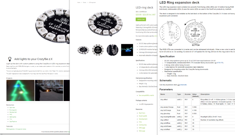
LED ring expansion deck in the main website, shop, and wiki.
Currently there are three different locations where you can find information about physical Crazyflie, localization systems or expansion decks, which is the main website, the online store and the wiki. We see that a lot of electronic and hardware shops usually put all the details of the product directly on the product page of their shops. We aim to do that as well, since there will only be one page for users to go to for schematics, specifications, instructions and more, and for us it will be also easier to maintain and update any product information
Moving Software Info to GitHub
There is a lot of bits and pieces of information to handle the firmware on the Crazyflie and all the tools in the tutorials on our main website, wiki and Github repository. This again makes a lot of duplicate information, which is difficult for us to maintain and therefore gets easily outdated. We could put all the information on the wiki, but what if somebody changes something in the code which requires a change in the procedure as well?
Create a /doc folder on the repositories to better structure all the information
Add more Doxygen comments to all the function in the the codes and automatically generate documentation for this.
Restructuring the Wiki Content
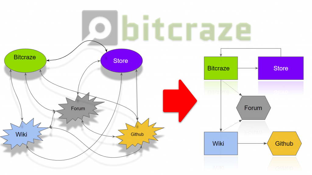
After moving all the hardware- related content to the shop, and moving all the firmwar- related info to the Github repositories, we will need to think about what we want to do with the Wiki! You would think that there is nothing left to put on the wiki anymore after the replacement of the earlier documentation, but we beg to differ! For instance, there is so many Github repositories that there is a really a need for an overview. The wiki can educate developers on which tools we have an how to properly use them. Of course, we already have the getting started tutorials, but we want to also provide a more in-depth explanation of the overall structure and how the different repositories would need tho work together, like this .
This does mean that we would need to restructure the wiki entirely and only focusing on topics like:
System Architecture Crazyflie
Communication protocol between STM and the NRF
Communication protocol between the Python library and the Client
Overview Github-repositories
Projects and hacks
etc etc
What do you think?!
Of course we can change all we want in the documentation, but you guys are the ones who actually use it! We are very curious of what what you think of the plans and give us more tips or suggestions on how to improve the overall documentation experience. Please leave a message below or express your opinion on this forum thread.
The High-level Commander has been part of the Crazyflie firmware since the 2018.10 release. In combination with a positioning system, it can fly the Crazyflie along a trajectory that is either defined in the firmware or uploaded through the python lib. It originates from the Crazyswarm project and we have used it in various demos since it is possible to make trajectories that are very fluid and looks really cool. The trajectories are defined as 7th degree polynomials describing segments executed one after each other.
The controller gives full control of position, velocity, acceleration and jerk, the only problem is that it is non-trivial to generate the polynomials. We have wanted to simplify the creation of trajectories for a long time and have finally had some time to play with it. In this blog post we will describe how it can be done with Bezier curves and show some examples.
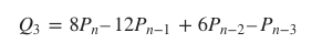
Each segment in a High-level commander trajectory is defined by four 7 degree polynomials, one for x, y, z and yaw. There is also a scaling parameter that tells the controller the time scale to use when executing the segment. Using polynomials of degree 7 makes it possible to design trajectories that are continuous in position, velocity, acceleration and jerk when changing from one segment to the next, which is important to get a smooth and controlled flight.
Bezier curves are common in many graphics applications and are probably known to most users. They are parametric curves defined by control points, usually three or four. Bezier curves can also be expressed as a polynomial, and this is what we will use in this case. To get a correct mapping to the desired polynomials we need some more control points and will use 8 per segment. The basic idea is to define the trajectory as Bezier curves and make sure the control points are placed in such a way that the continuity requirements are satisfied.
Bezier curve with 8 control points
On this page from University of Cambridge, there is a good explanation on continuity across the joins between curves and formulas for c0, c1 and c2 continuity. We also need c3 continuity which can be calculated in the same manner
With these formulas it is possible to set the handles of the Bezier curves to make sure we get a smooth ride.
We have added a python example that implements the ideas above. You can find it in crazyflie-lib-python/examples/positioning/bezier_trajectory.py. The design is based on Nodes that represents the connection points between bezier curves (called Segments). The Nodes has a set of handles that are shared between the Segments that use the Node. If not all handles are set the implementation will set them to appropriate values, see the comments in the code for more details. The Node API only allows the user to set handles on one of the Segments, the handles for the other segment are automatically set to generate a continuous trajectory.
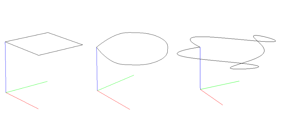
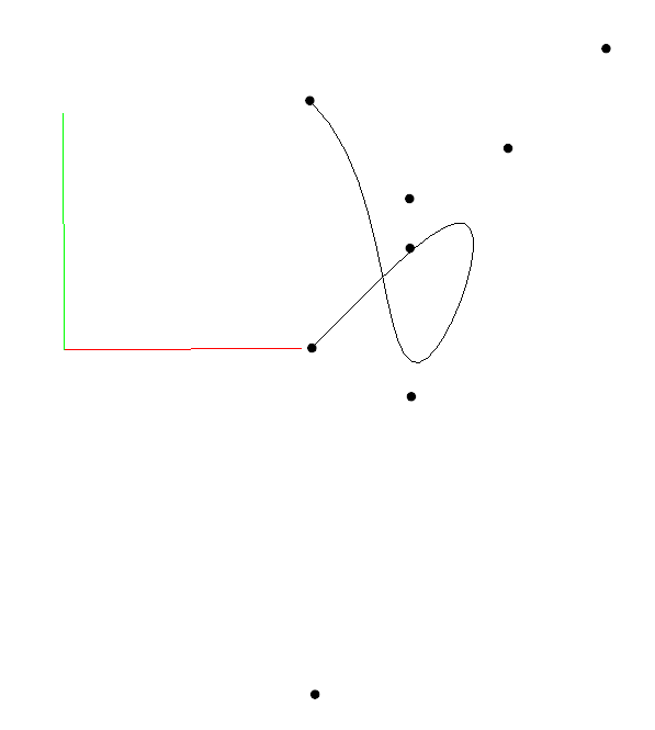
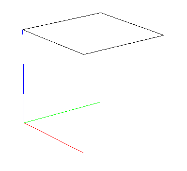
The example uses nodes in the corners of a square and contains three parts:
No velocity in the nodes. The Crazyflie stops in the Nodes. Similar to calling go-to in the HL commander.
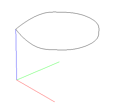
Velocity in the nodes. A fluid motion all the way around.
Velocity in the nodes. A fluid motion all the way around.
A bit more aggressive settings to get a little action.
Finally a video showing the full sequence, we use the Lighthouse for positioning.