Quantcast
Channel: Crazyflie – Bitcraze
Viewing all 456 articles
Browse latest View live

Crazyflie 2.0 as an autonomous flying platform

$
0
0

Crazyflie has been used by hackers and researchers as an autonomous flying platform for a while, though it has required expensive or very special software and equipment. Universities and the industry have, in most cases used motion capture systems that are very precise but also comes with a hefty price tag. We have developed the Loco Positioning System as a more accessible way to achieve autonomous flight with the Crazyflie. Bitcraze has worked intensively with autonomous flight and together with the community, we have added a number of advanced algorithms to the Crazyflie firmware that not only serve the Loco Positioning System, but are useful for anyone interested in autonomous flight regardless of positioning system. The functionality is useful for anyone from researchers with motion capture systems to hackers with a couple of webcams!

Lately there has been a lot of activities around control and stabilization algorithms. The main piece of software that has been merged into the Crazyflie firmware is the Extended Kalman Filter. With it, the Crazyflie uses its inertial sensor together with positioning information in order to calculate an estimated position. One great advantage of the Kalman filter is that it can handle much lower quality or intermittent position measurements and still fly autonomously. Of course the better the position information, the better the flight performance, but things like camera tracking with occlusion becomes possible.

There has also been a lot of work on a new controller. The controller is the piece of software that looks at the position estimate and calculate control commands to reach a given set point (for example go to {x;y;z}). We are currently working on adapting the firmware architecture to merge a more advanced control algorithm that supports complex trajectory following capabilities

Finally there is a new commander architecture that adds the possibility to send complex set points to the Crazyflie via the radio. For manual flight all you need is 3 angles, roll/pitch/yaw, and the thrust. For a more advance controller you might need position, velocity and acceleration in X/Y/Z. For even more complex trajectories, we are working at merging a sequence generator to which we can send high level setpoints like spline coordinates. The sequence generator will calculate the required setpoints onboard in real time to follow the trajectory.

All these algorithms are currently work in progress, they are in various stages of completeness, but for example we have had the Crazyflie following circles in our lab last week using the on board sequence generator, so things work. However getting the code to work is only the beginning, until it is in the master branch it does not exists. Once the code land in master, like the Kalman filter did a while ago, it will be useful out of the box for anyone that wants to work with autonomous flight using any kind of localization system: Loco Positioning, Motion Capture, GPS, webcam, etc …


Collaborate with us!

$
0
0

Lately the Crazyflie has been used more and more as a demonstration and reference platform by a number of sensor manufacturers, including Bosch Sensortec. The possibility to add expansion decks to the platform and that the project is open source makes the Crazyflie very suitable to test and demonstrate new sensors in real time. For us this is a further confirmation of the strengths of working with open source and it enables us to provide the community with new and cool expansion decks as early as possible.

We are glad that the industry sees the value in our open source project and is interested in collaborating with us. This will enable us to continue to evolve this and other exiting new hardware project in the future. If you and your company is interested in a collaboration, please read more on our “Used by the industry” section. 


Porting the Crazyflie client to Qt5

$
0
0

The Crazyflie client, the software running on a computer that is used to control and get telemetry from the Crazyflie, is written in Python and used PyQt4 as graphical user interface framework. This has worked quite well and has the advantage of running on windows/mac/linux without much effort. However Qt5 and PyQt5 have been released for a long while now and what should happen is starting to happen: PyQt4 is starting to get depreciated.

The first sign came from macOS, a ticket was reported on the Crazyflie client github indicating that it was not possible anymore to install PyQt4 using the Homebrew package manager. The problem was solvable since PyQt4 was still there but moved in the Homebrew ‘backyard’, so for the time being it still works but is a bit worrying. More recently Python 3.6 was release and there will apparently not be a release of PyQt4 for Python 3.6, this means that if we do not do anything the client risk to not be supported on linux anymore (the next Ubuntu LTS is planned to use Python 3.6).

This was enough to push us to port the client to the new Qt/PyQt5. The port was started by sighmon when the first macOS related ticket was reported but we had a bad bug with the Gamepad reading on macOS, this bug was the main blocker but has been fixed last week so we are now very close to having the port functional!

If you are curious about it, we have the port in a branch on github. We are planing on merging it in the following days and releasing a new version of the client in the process.

We are also planing on releasing a Windows build and installer this time. The Windows installer has been built automatically in AppVeyor for a couple of month now and it seems stable enough to become an official version. We still want to make a macOS app out of the client but are still blocked in doing so. If you have experience making macOS app out of PyQt5-based software, we would greatly appreciate some help in getting a mac build, we have a github ticket for it.

Autonomous photo shoot

$
0
0

Early on when we started to work on the Loco Positioning system, we came up with an idea of a Crazyflie autonomously flying into a light box, positioning it self for a few product pictures and then flying out again. The positioning system is now pretty mature and close to leave Early Access and this Friday we finally got around to do it. In this blog post we will share what we did and it also doubles as a brief howto on how to set up the system and fly a simple autonomous sequence.

We used a Crazyflie with a Loco Positioning Deck and eight Loco Positioning Anchors in our setup. Six anchors would have been fine too, but we happened to have eight in our flight lab.

When working with the Loco Positioning system the first step is always to make sure the anchors are set up correctly. We had an experimental version of the anchor firmware so we started out by pulling down the latest stock version of the source code and compiled it into a .dfu file. After that we fired up the brand new lps-tool that is used to flash firmware and configure the anchors. The anchors must be connected with a USB cable to the computer but the lps-tool reduces the flashing and configuration into a few clicks. When all anchors were updated we were ready for the next step.

The positions of the anchors are stored in the anchors them selves and the position is transmitted to the Crazyflie as a part of the ultra wide band messages used for measuring the ranges to the anchors. This way, the Crazyflie gets both anchor positions and ranges in the same process and has all the information needed to calculate its position. The second step is thus to store the positions in the anchors. In our “flight lab” we have fixed mounts for the anchors with known positions, so we could skip measuring the physical positions of the anchors.

We are working on making it possible to remotely configure the anchors to reduce the need to physically connect to them, and the position can now be set from the Crazyflie Client. We simply opened the “Loco Positioning” tab in the client, connected to a Crazyflie (with a Loco Positioning deck mounted), entered the anchor positions and hit the “Write to anchors” button. A few seconds later the anchor positions in the graphs were updated to indicate that the positions have been written to the anchors and then subsequently sent back through the ultra wide band messages to the Crazyflie.

Step three is to verify that the system is working as expected. First thing is to check that we did not mix the anchors up when configuring or placing them. In the “Loco Position” tab in the client, click the “Anchor Identification” button. In this mode anchors are lit up in the graphs when the Crazyflie gets close to them in the physical world. We went from anchor to anchor with the Crazyflie and checked that the correct anchor lit up on the screen. When confident that all was good we changed to “Position estimate” mode and verified that the estimated position matches the physical position of the Crazyflie. We have found that it can be very hard to understand, for instance that two anchors have been mixed up, by looking at the estimated position and that the “Anchor Identification” step simplifies the setup.

At this point we had a fully functioning Loco Positioning system ready for autonomous flight!

Now it was time to script a sequence. The easiest way to script a sequence is to start from the autonomousSequence.py example. Our intern Alfred took over at this point, he updated the uri to the correct settings and crafted a sequence to take off, fly into the light box, wait a while and then fly back out for a stylish landing in his hand!

Now we were ready for the actual photo shoot and Björn came down with the camera to shoot the product pictures. We hope you enjoy the results!

Updated autonomous flight using OpenCV and Kalman filter

$
0
0

At Bitcraze we have some history with trying to fly our Crazyflie autonomously. The most recent step is the Loco Positioning System that allows us, and you, to fly in a full room. The Loco Positioning system has boosted development of advanced algorithms for onboard position estimation and control.

Our earlier attempts where mostly based on different kinds of cameras, either a 3D camera like Kinect or regular webcams. Though, at that point, we only had the camera for position estimation and where doing the position control on the PC and not onboard the Crazyflie. This has the disadvantage to be brittle and requires a very high quality positioning from the camera: any frame where we loose the Crazyflie has a huge impact on the control behavior since the position controller relies exclusively on the camera detection.

With the Kalman filter and onboard position controller, the Crazyflie can now handle lost position information for at least a couple of seconds without big problems. This has the potential of making webcam-based position detector much more robust!

To test this theory we have grabbed the 2 years old crazyflie-ar-detector from the dawer github, updated it to OpenCV 3.2.0, and fed the position output to the Crazyflie 2.0 external position port. The crazyflie-ar-detector program is using ZeroMQ to communicate position and so we made a simple external position tab for the Crazyflie Client that receives position from ZeroMQ and sends it to the connected Crazyflie.

Using the new position-hold mode recently introduced in the client we can test and fly the Crazyflie under the webcam. We have taken a short video to show the performance. The result is promising and we will continue to play with ways to fly the Crazyflie autonomously.

Z-ranger deck now availible

$
0
0


For those of you out there that are new to flying drones the height is often the most difficult thing to control. One solution to that problem is our newly released Z-ranger deck that can precisely measure the distance to the ground. Using this information the drone itself can stabilize on a desired target high and therefore become much easier to control. The Crazyflie 2.0 will then behave similar to a hovercraft sweeping over the ground or climbing stairs which is a ton of fun. As an in-action example please check out the video below where a Crazyfie 2.0 with a Z-ranger e.g. follows a flight of stairs :-).

For information of how to activate the height hold mode have a look at the getting started guide and for further details please check out the Z-ranger wiki page.

Crazyflie firmware and client release 2017.4 with Z-Ranger support

$
0
0

We are happy to announce that we have released new versions of the Crazyflie Firmware and the Crazyflie client, both are now in version 2017.4. The main feature of the release is support for the new Z-Ranger deck.

To support the Z-Ranger, a new flight mode has been added to both the firmware and the client: the Height-hold mode. This mode allows to fly with the Z-ranger deck at a fixed height above the floor.

There are also a number of other improvements and bug fixes in the releases, mainly related to the Loco Positioning system and autonomous flight.

On the client side, this new release is also a come-back of the windows build. It means that it is now easier to get started and fly your Crazyflie directly from Windows as you can install it as a native app. We really want to build the client for Mac OS too but have met some problems. If anyone has experience in building pyqt apps for mac OS, with your help we might be able to have a mac build for the next client version ;-).

For instructions on how to upgrade see the getting started guide.

Have fun!

Crazyradio: past, present and future

$
0
0

The past

The Crazyradio has been designed as a radio dongle to control the original Crazyflie 1. It is based on a Nordic Semiconductor nRF24LU1. It is basically the radio from Crazyflie 1, the nRF24L01, with a microcontroller and a USB device peripheral. Crazyradio has been designed from the beginning to be extended for other used: the code is completely open-source, can be powered with 12V and has an expansion port with possibility of implementing a serial port to communicate with the radio.

When we designed Crazyflie 2.0, we extended Crazyradio to make Crazyradio PA. It is basically the same hardware but we just added a power amplifier to make sure Crazyradio is transmitting with the same power as competing radio in the same 2.4GHz band: Wifi and Bluetooth. Crazyflie 2.0 is not using an nRF24 chip anymore but an nRF51822 which integrates a microcontroller and implements bluetooth low energy as well as nRF24 compatible radio.


The present

The Crazyradio (PA) has been used for a couple of hack like our glove controller. Another popular use has been by security researcher to experiment with the security of wireless mouse and keyboard. Indeed the nRF24 serie of chip is extensively used in wireless mouse, keyboard and even quadcopters ;).

We are often very quiet about the Crazyradio since ‘it just works’. It does not means that it is finished or perfect, there is actually a lot that was planned to make the radio link more efficient, to be able to control more Crazyflie per Crazyradio, etc… Some of this work has been done in the context of the Crazyswarm project by Wolfgang from USC but a lot more could be done. One of the main blockers for Crazyradio development is that it is based on a very old microcontroller, an 8051, and that it does not have a safe bootloader or (open) debugging access. It means that each modification is potentially a big commitment in time and since the radio already work quite well it is hard to put much time in it.

The absence of a safe bootloader means that if you flash a firmware that crashes, you will need an SPI programmer to recover the radio in working mode. This makes it quite stressful to work with the radio. However there are a couple of programmers made for this and we recently published a Hackster project about using a Raspberry Pi to recover the bootloader:

The future

We have been looking at making a Crazyradio with an nRF51-series chip, these chips have a Cortex-M0 CPU which means that they are much easier to program using a modern development environment. However none of the chip in the nRF51 series have USB which forced us to prototype the concept with an added microcontroller for USB. This creates a bigger and more populated Crazyradio:

We did not like this design very much since having 2 microcontrollers is always much more haste to program, debug and maintain. Thankfully Nordic semiconductor will release a nRF52 chip with USB support. Adding to that a powerful Cortex-M4 microcontroller, a lot of ram, still Bluetooth low energy and nRF24 radio compatibility but they also added iEEE802.15.4 2.4GHz (ie. the protocol used by Zigbee). This new chip is a very good candidate for the next Crazyradio.

We are very much in the pre-study phase for the next Crazyradio (and mass production for the new nRF52 is planned for Q4 2017 anyway…), so if there is functionality that you would like to see in a future Crazyradio it is time to speak up! Please tell us in the comment section bellow or in the forum ;-).


Loco positioning tag

$
0
0

Ever since we released the Alpha round of the Loco positioning system we’ve been talking about designing a more generic tag that could be used together with other robotics platforms for local positioning. We did a quick design of a prototype that we tested, but with the workload involved in bringing the LPS out of Early Access, finishing the Z-ranger and lots of other stuff , it’s remained on the shelf. But recently we’ve been getting more and more requests for this kind of hardware, so we thought it might be time to dust off the prototype and try to release it. One of the blockers (except workload) has been that we’re not sure how the tag should look mechanically and how to interface it electrically for it to be as useful as possible for our community. This post is for detailing the current status of the hardware/firmware and to see if we can get some feedback on what our community would like the finished product to look like.

The hardware

To make use of the firmware that’s been developed so far for the Crazyflie and the Loco positioning we aimed at making something similar to what we already have but with another form factor and slightly different requirements. As you might know the Loco positioning node can be configured as a tag, but there’s two drawbacks that we wanted to fix. First of all the Loco positioning node might be a bit big to put on smaller robots. Secondly the Loco positioning node can only measure the distances to the anchors, it doesn’t have an IMU to get attitude of the board and doesn’t have the processing power to run the same algorithms we have on the Crazyflie 2.0.

So for our Loco positioning tag prototype we decided to fix these. The prototype has the same sensors as the Crazyflie 2.0: Gyro, accelerometer, magnetometer and pressure sensor. It also has the same MCU as the Crazyflie 2.0: STM32F405. In addition to this it has the DWM1000 module for the ultra wide-band radio (used for positioning). We’ve also added the interfaces we have on the Crazyflie 2.0: SWD debugging, micro-USB for communication and power as well as a button. Looking at the pictures below you might also notice that we’ve added the Crazyflie 2.0 deck connector. So does this mean you can connect it to the Crazyflie 2.0? No, well not this prototype at least. The reason for adding it was we wanted to be able to use the same expansion decks as for the Crazyflie 2.0. So it’s possible to add the breakout deck for breadboard prototyping or the LED-ring for visual feedback.

So what’s the status of the hardware? Even though it’s the first prototype it’s fully functional and will give you positioning and attitude. What’s left is defining the electrical interfaces and the form-factor of the board so it can easily be attached to what ever you might want to track. The images below shows a side-by-side comparison with the current Loco positioning deck.

Loco positioning tag (on the right) compared to Loco positioning deck (on the left) (FRONT)

Loco positioning tag (on the right) compared to Loco positioning deck (on the left) (BACK)

The firmware/software

Like I wrote above we wanted to reuse as much of the firmware and software as possible. So the firmware running on the prototype is just a scaled down version of the Crazyflie 2.0 firmware. As you might have noticed the prototype looks a lot like the Crazyflie 2.0, except that it’s not a quadcopter and doesn’t have the nRF51 radio. So by “scaled down” I mean we’ve removed the motor and radio drivers, that’s about it. So how do you communicate with it? Well you can use one of the protocol available on the deck connector: SPI, I2C or UART. But the currently implemented way is using USB. Since it’s basically a Crazyflie you can use our client and python libraries to set parameters and log data values from it.

Conclusion

The current prototype is basically a USB dongle where you get position and attitude. It could easily be connected via USB to a Raspberry Pi, Beaglebone or any other SoC based platform or a computer. You can also interface it from an Arduino using the peripherals on the deck connector. The firmware is working and using the python library (or any other of our community supported libraries) you can easily get the position and attitude of the board. But to be able to take the next step and make something our community could make the most of we would love some feedback on the prototype. What kind of electrical interfaces and form-factor would you like?

Meet us in Singapore!

$
0
0

We are going to the IEEE International Conference on Robotics and Automation in Singapore. The exhibition is open Tuesday May 30 to Thursday June 1 and we will have a booth, number C08, where we will show demos and discuss our work, positioning technologies and quadcopters.

We have not finalized our demos yet but they will include autonomous flight with the Crazyflie and the Loco Positioning system. We also hope to show our brand new optical flow expansion deck that will enable positioning and autonomous flight when on a tight budget. We also plan to show integration with external computers running ROS or our own python library. If we are lucky there might even be a small swarm, even though the space is very limited.

We love to talk to people that are using our products or just interested in our technology, if you are at the conference please drop by and say hi and tell us what you are working on. We will arrive in Singapore on Saturday morning May 27, and if you want to hook up and say hi and have a coffee during the weekend, drop us an email.

See you in Singapore!

Demo for ICRA 2017

$
0
0

A couple of weeks ago we played with recording and retracing trajectory directly from the Crazyflie using Loco Positioning System. The result was quite nice and resulted, a first for us, in a fully autonomous Crazyflie, no computer or controller required:

We decided to expand on this experiment for our demo at ICRA. We have modified the retracing code to accepts multiple modes, including running pre-programmed sequence. The plan for the demo is to have Crazyflies that can:

  • Record and retrace a manual trajectory
  • Record and replay in a loop a manual trajectory
  • Play a pre-defined trajectory in a loop
  • Land automatically when the battery level is low

With this we should be able to demonstrate quite well the capabilities of both the Crazyflie and the Loco Positioning system, and since we do not require a computer in the loop it simplifies a lot running the demo. Of course we keep the possibility to connect the Crazyflie with the Crazyflie client and with ROS while the crazyflie is flying.

Having a completly autonomous Crazyflie is also new to us and it brings its share of problems: how to we choose the working mode and how to we stop the flight if something happens (things tends to happen …).

To solve the former we have made a button deck that adds 2 push-button to the Crazyflie. One means “Start autonomous sequence”. The second means “Record trajectory”. If the recorded trajectory is a loop (if the end point is close to the start point) then the loop is played back as soon as the crazyflie is dropped, otherwise Crazyflie retraces the trajectory and stop.

We solved the later problem by making an autonomous emergency stop button that sends a radio watchdog signal. If the signal stops to be sent or if an emergency stop signal is sent (ie. by pressing the button), the Crazyflie will stop all motors and drop. The button is implemented using a Raspberry pi, a Crazyradio and an Arduino to interface the button:

If you are curious about code, we have created a github repos where we push all code we are making for this demo. As usual, this conference is an opportunity for us to hack new functionalities, though not everything can be done in the master branch. Later some things can be merged, others (like the retrace trajectory recorder/player that looks more like a user app.) will need much more though if we want to merge it in the Crazyflie firmware.

Loco positioning out of early access!

$
0
0

We have been working with our indoor positioning system for over a year now and during that time the interest for the Loco positioning system have continuously been growing. Universities all over the world are already using our system and the attention we have received have been very encouraging. But the system has been a bit hard to set up and lacking in documentation. So we decided that this had to be fixed before we could leave early access.

So now we’re happy to announce that the Loco positioning system has reached a state where it’s out of “Early access” and we’re excited to see even more customers starting to use the system. We would like to thank everybody in the community that has been contributing to the project, this is what makes open source great!

Below are some of the steps we’ve taken to make it easier to use.


Getting started guide

We have created a brand new “Getting started with Loco positioning” tutorial that will replace the old “Getting started” video that we made. The tutorial contains a step-by-step guide for flying one Crazyflie 2.0 autonomously using two way ranging. The more advanced features such as TDoA is still considered as experimental and won’t be covered in this tutorial. We are very happy with the outcome of this tutorial but please help us out and try the tutorial and give us feedback.  

LPS tool

In order to easily configure and upgrade the firmware for the Loco positioning nodes we’ve created the LPS tool. With it you can set the address of the node, the mode and also upgrade the firmware easily. 


LPS tab

Up until lately there hasn’t been any support for the Loco positioning system in our Crazyflie Python client, instead we’ve been using ROS. It’s a great tool and very powerful tool, but ROS can be a bit complicated with specific requirements on the environment in which it runs. So we wanted to be able to perform basic use-cases directly in our client, like setting up the system, debugging it and flying with it. In order to achieve this we created the Loco positioning tab and a new flight mode called Position hold.

The Loco positioning tab is used to set-up the system and view it’s status. You can configure the position of the anchors, easily see which anchors you’re close to and if all the anchors are responding as they should. It’s also possible to see the layout of the system and the Crazyflies position in it.

For flying the Crazyflie we’ve added the Position hold mode. When enabled this will translate gamepad input into velocity control set-points that are followed using the positioning.


Wiki documentation

We’ve added technical documentation for the Loco positioning system to the wiki and we’ve also created product pages with schematics and details on the hardware for the Loco positioning node and deck. In the documentation you can find useful things like protocol documentation and details on our reference set-up that we use in our lab. Sine the system is still continuously evolving this is a working document that will continue to be improved over time and we hope to push the boundaries further for swarm flying and robotics in general.

ICRA

Finally a reminder, if your are attending 2017 IEEE International Conference on Robotics and Automation in Singapore you can meet us in booth C08 from 30/5 – 01/6. We will show autonomous flight with the Crazyflie 2.0 enabled by the the Loco Positioning System. Come by have a chat with us and see the Loco positioning in action!

You will also be able to attend the presentation of the paper “Crazyswarm: A Large Nano-Quadcopter Swarm” by researchers from USC during Wednesday 31/5 at 11:15.

Releases

To support the features mentioned above we’ve released version 2017.05 of the Crazyflie Python client and Crazyflie firmware.


ICRA 2017

$
0
0

We exhibited at the IEEE International Conference on Robotics and Automation in Singapore a couple of weeks ago.

We had a booth where we demoed autonomous flight with the Crazyflie 2.0 and the Loco Positioning system, without any external computer in the loop. The core of the demo was that the Crazyflie had an onboard trajectory sequencer that enabled it to fly autonomously along a path, based on the position from the Loco Positioning system.

We had a pre programmed path that we used most of the time, since it enabled us to start the demo and the leave the Crazyflie without any further manual interference from our side (except changing battery). The other option was to manually record a path for the Crayzflie to retrace by moving it around in the flying space. When we dropped it (detecting zero gravity) the onboard sequencer and controller took over to replay the recorded path. This mode was very useful when showing the accuracy and performance of the system by recording a short sequence of one point and just leaving the Crazyflie to hover. We had mounted a deck with two buttons on the Crazyflie that we used to chose which mode to use.

The code used for the demo is available at github for anyone to play with.

Optical flow

We also showed our brand new Flow deck that we will release soon. It is a deck that is mounted underneath the Crazyflie with a downwards facing optical flow sensor. The sensor is in essence what is used in an optical mouse but with a different lens that enables it to track motion further away. The output from the deck is delta X and Y for the motion of the Crazyflie and can be used by the onboard controller to control the position. We will publish more information in this blog soon.

We had a great time talking to all you interesting, bright and awesome people. Thanks for all feedback, sharing ideas and telling us about your projects!

Prototype of a brushless Crazyflie

$
0
0

For a while now we have been selling the BigQuad deck which makes it possible to transform the CF2 to control a bigger sized drone. It does so by becoming the quadrotor control board, controlling external brushless motor controllers, which allows to scale up the size. This can be very convenient when trying out/developing new things as it first can be tested on the small CF2 and later scaled up by attaching it to a bigger quad. However for a more permanent setup it is a bit bulky, so we have been playing around a bit and designed something in the middle. The result is a stand alone control board targeting quads around 0.1 – 0.5kg.

We call it the CF-RZR as it is inspired by the smaller sized racers with some fundamental differences. It is designed with a higher level of autonomous functionality in mind and being easy to repair while still being fully compatible with the CF2 firmware and decks. Listing the biggest features of the current prototype:

  • Fully compatible with the CF2 firmware, expansion decks as well as radio.
  • Connectors to attach motor controllers (still possible to solder though) so it is easy to build and repair.
  • Power distributions built into controller board. (Max ~8A per motor controller though)
  • Motor controllers can be switched of by the system so the system can go into deep sleep and consume around 50uA.
  • Voltage input 1S-4S (3V to 17V)
  • Standard mounting (M3 mounting holes placed 30.5mm square)
  • External antenna for increased range

To summarize, the strength of the CF2 but in a little bit bigger package :-). Last week we got a chance to test fly it for the first time. We used a off the shelf racer frame, ESC and motors. At first it did not fly that well at all but after some PID tuning it became pretty stable and we had a lot of fun :-).

We would love your feedback, good/bad idea, what do you like/dislike etc!

Link to video

Towards Persistent, Adaptive Multi-robot Systems

$
0
0

This week’s Monday post is a guest post written by members of the Robust Adaptive Systems Lab at Carnegie Mellon University.

As researchers in the Robust Adaptive Systems Lab (Director: Prof. Nathan Michael) at Carnegie Mellon University http://rasl.ri.cmu.edu, we’re interested in developing algorithms for control, planning, and coordination to enable robots to adapt to their environments, and we use the Crazyflie platforms to help us test our theory on real world systems.

We employ Crazyflie quadrotors to evaluate several research objectives in our lab. One research thrust looks at enabling a platform to learn new controllers as it flies, allowing the quadrotor to automatically switch between controllers to handle specific flight conditions. Another objective looks at adapting flight plans for multiple robots in real time, based on what a user tells the robots to do. We use the Crazyflie platform to evaluate our algorithms because the hardware is robust and the user community has helped make firmware available on which we can base our own systems (J. A. Preiss, W. Hönig, G. S. Sukhatme, and N. Ayanian. “Crazyswarm: A Large Nano-Quadcopter Swarm,” ICRA 2017. https://github.com/USC-ACTLab/crazyswarm). At the same time, the power and memory constraints of the Crazyflie force us to pursue efficient algorithms that can handle real world considerations such as limited battery life and computing restrictions.

We’re bringing these research ideas together to make an adaptive multi-robot system that a person can direct online and operate over long periods of time–longer than the lifespan of a single battery. In this blog post, we wanted to share a bit of information about some of the research we’re working on that uses the Crazyflie platforms. We look at single-robot controllers, multi-robot planning systems, and hardware designs to move us towards a persistent, adaptive swarm of Crazyflies.

Control Approaches

We have looked at implementing advanced control strategies onboard the Crazyflie for improved safety and flight performance. This includes an extremely efficient formulation of explicit Model Predictive Control (MPC) developed specifically for systems like the Crazyflie that have severe computational constraints due to size, weight, and power limitations. MPC optimizes the control commands based on current and predicted motion, allowing us to enforce speed limits and avoid motor saturation. The controller is run in a separate task on the STM32F405 MCU, allowing it to maintain a 100 Hz position control rate without blocking other components, such as the state estimator and attitude controller.

In the image above, the vehicle uses MPC control to rapidly and accurately move between two destinations. [V. R. Desaraju and N. Michael, “Fast Nonlinear Model Predictive Control via Partial Enumeration,” ICRA 2016.]

Multi-robot Systems

Another element of our research emphasizes adapting plans for multi-robot systems online, in order to translate a human operator’s intent into dynamically feasible and safe motion plans. We are using a swarm of Crazyflies for hardware validation of the online motion planning algorithms.

Our experimental testbed consists of a Vicon motion capture system that provides the state information (position and orientation) of the robots. The position coordinates and the heading angle are broadcast to the individual Crazyflies using the radios at a rate of 100 Hz. A centralized planner, running on a separate thread, parses user instructions into dynamically feasible and safe motion plans for each individual robot. The user instructions consists of high level information such as robot ids, behavior type (go to a target destination, rotate in a circle), and formation shapes (line, polygon, 3D). Once the feasible and safe motion plans are computed, the desired position setpoints are broadcasted to the Crazyflies at a rate of 30 Hz.

These images show a formation of 30 Crazyflies in a 3D shape and five groups of three Crazyflies, flying around a motion capture arena in response to a user’s direction. The multi-robot planner computes these flight plans online in response to the user’s commands, without any prior planning. [Ellen A. Cappo, Arjav Desai and Nathan Michael. “Robust Coordinated Aerial Deployments for Theatrical Applications Given Online User Interaction via Behavior Composition,” DARS 2016.]

Hardware Considerations 

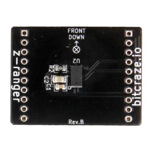
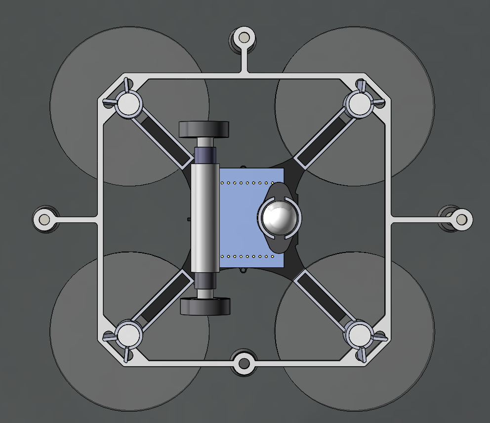
As we move towards operating for long periods of time, we needed to incorporate the Qi inductive charger to enable the robots to recharge. We also want to retain the LEDs, to keep an aesthetic visual element and act as status indicators. There were two concerns with using both the standard LED and Qi decks: they both mount to the bottom of the Crazyflie, and both decks add weight. We created a combined deck based on the schematics from the Bitcraze wiki, and the final deck is shown below and weighs in at 6-7g.

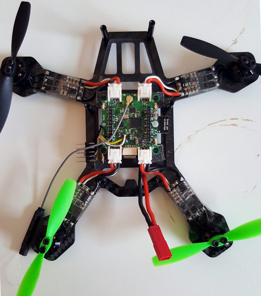
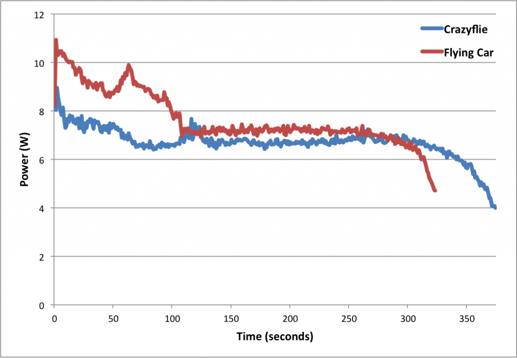
Even with the combined Qi + LED deck, we observe shorter flight times and motor saturation with the Crazyflie flights, so we increased the battery capacity and flying with different motor and propeller combinations. Pictured below is a Crazyflie with 7×20 motors using 55mm propellers and a 500mAh battery, and carrying a foam mount for the motion capture markers. No frame modifications are required as the motors fit in the mounts and the battery is chosen to fit within the header pins. These changes resulted in an increase in flight time, greater control margin and aggressiveness, and larger payload capacity.

Toward Persistent Operation

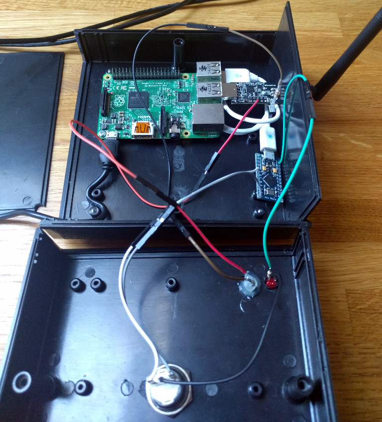
The capabilities we mentioned above allow us to work towards long duration operation. We are currently integrating our adaptive control, online planning, and efficient hardware design to enable persistent operation of a swarm of Crazyflies. To achieve this goal, we are developing scheduling algorithms that update flight plans based on battery capacities across a Crazyflie fleet. The flight planner calculates trajectories that allow robots with full batteries to exchange places with robots with expired batteries, landing Crazyflies that need to recharge onto charging stations. In the first image below, 10 robots rotate in a circle formation. The time-lapsed image shows three Crazyflies with full batteries (with blue LEDs) exchange places with three Crazyflies with depleted batteries (with red LEDs). The second photo shows a close-up of our Crazyflie charging station.

In closing, we show a few video clips of Crazyflie flight illustrating the research we discuss here. We show a group of fifteen Crazyflies following online-issued commands to split and merge between formations; a formation of 30 Crazyflies; and an example of our exchange planner, substituting robots into a multi-robot formation and returning robots to ground station locations.

Contributors: Ellen Cappo, Arjav Desai, Matt Collins, Derek Mitchell, and Vishnu Desaraju, students and researchers at the Robust Adaptive Systems Lab (Director: Prof. Nathan Michael), Carnegie Mellon University.


Qualisys visiting Bitcraze

$
0
0

A couple of weeks ago Qualisys visited us at the Bitcraze office, they came with the Miqus motion capture system that they installed temporary in the office. This gave us the opportunity to play with their motion capture system and the Crazyflie 2.0 :-).

It was our first hands-on experience with a motion capture system. We were eager to try the algorithms that have been developed for the loco positioning system with the more precise position information offered by the motion capture. The result was above our expectations. You get a bit amazed when it is just sitting there in the air. The normally difficult in-air photo shoot became a breeze since you suddenly have plenty of time to focus and shoot.

After running a couple of simple stabilized flight demos, we endeavored to run the ICRA demo with motion capture instead of our loco positioning system. As the loco positioning deck isn’t needed it was removed and instead the measured position was sent using Crazyradio. Doing so made the demo work pretty much out of the box. The ICRA demo had 2 buttons, one for playing a pre-recorded trajectory and one for recording a path and playing it back as soon as the Crazyflie is dropped. Both modes worked seamlessly without requiring any code change. We tried the path recording and playback functionality and were pretty impressed by the precision:

Link to video

We look forward of meeting and working more with Qualisys. One goal is to provide better information, documentation and tools to get started with Crazyflie in a motion capture system.

Multi-robot Path Planning for Flying-and-Driving Vehicles

$
0
0

This week’s Monday post is a guest post written by members of the Computer Science and Artificial Intelligence Lab at MIT.

One of the focuses of the Distributed Robotics Lab, which is run by Daniela Rus and is part of the Computer Science and Artificial Intelligence Lab at MIT, is to study the coordination of multiple robots. Our lab has tested a diverse array of robots, from jumping cubes to Kuka youBots to quadcopters. In one of our recent projects, presented at ICRA 2017, Multi-robot Path Planning for a Swarm of Robots that Can Both Fly and Drive, we tested collision-free path planning for flying-and-driving robots in a small town.

Robots that can both fly and drive – in particular wheeled drones – are actually somewhat of a rarity in robotics research. Although there are several interesting examples in the literature, most of them involve creative ways of repurposing the wings or propellers of a flying robot to get it to move on the ground. Since we wanted to test multi-robot algorithms, we needed a robot that would be robust, safe, and easy to control – not necessarily advanced or clever. We decided to put an independent driving mechanism on the bottom of a quadcopter, and it turns out that the Crazyflie 2.0 was the perfect platform for us. The Crazyflie is easily obtainable, safe, and (we can certify ourselves) very robust. Moreover, since it is open-source and fully programmable, we were able to easily modify the Crazyflie to fit our needs. Our final design with the wheel deck is shown below.

A photo of the Crazyflie 2.0 with the wheel deck.

A model of the Crazyflie 2.0 with the wheel deck from the bottom

The wheel deck consists of a PCB with a motor driver; two small motors mounted in a carbon fiber tube epoxied onto the PCB; and a passive ball caster in the back. We were able to interface our PCB with the pins on the Crazyflie so that we could use the Crazyflie to control the motors (the code is available at https://github.com/braraki/crazyflie-firmware). We added new parameters to the Crazyflie to control wheel speed, which, in retrospect, was not a good decision, since we found that it was difficult to update the parameters at a high enough rate to control the wheels well. We should have used the Crazyflie RealTime Protocol (CRTP) to send custom data packages to the Crazyflie, but that will have to be a project for another day.
The table below shows the mass balance of our miniature ‘flying car.’ The wheels added 8.3g and the motion capture markers (we used a Vicon system to track the quads) added 4.2g. So overall the Crazyflie was able to carry 12.5g, or ~44% of its body weight, and still fly pretty well.


Next we measured the power consumption of the Crazyflie and the ‘Flying Car.’ As you can see in the graph below, the additional mass of the wheels reduced total flight time from 5.7 minutes to 5.0 minutes, a 42-second or 12.3% reduction.

Power consumption of the Crazyflie vs. the ‘Flying Car’


The table below shows more comparisons between flying without wheels, flying with wheels, and driving. The main takeaways are that driving is much more efficient than flying (in the case of quadcopter flight) and that adding wheels to the Crazyflie does not actually reduce flying performance very much (and in fact increases efficiency when measured using the ‘cost of transport’ metric, which factors in mass). These facts were very important for our planning algorithms, since the tradeoff between energy and speed is the main factor in deciding when to fly (fast but energy-inefficient) versus drive (slow but energy-efficient).

Controlling 8 Crazyflies at once was a challenge. The great work by the USC ACT Lab (J. A. Preiss, W. Hönig, G. S. Sukhatme, and N. Ayanian. “Crazyswarm: A Large Nano-Quadcopter Swarm,” ICRA 2017. https://github.com/USC-ACTLab/crazyswarm) has made our minor effort in this field obsolete, but I will describe our work briefly. We used the crazyflie_ros package, maintained by Wolfgang Hönig from the USC ACT Lab, to interface with the Crazyflies. Unfortunately, we found that a single Crazyradio could communicate with only 2 Crazyflies at a time using our methods, so we had to use 4 Crazyradios, and we had to make a ROS node that switched between the 4 radios rapidly to send commands. It was not ideal at all – moreover, we had to design 8 unique Vicon marker configurations, which was a challenge given the small size of the Crazyflies. In the end, we got our system to work, but the new Crazyswarm framework from the ACT Lab should enable much more impressive demos in the future (as has already been done in their ICRA paper and by the Robust Adaptive Systems Lab at Carnegie Mellon, which they described in their blog post here).

We used two controllers, an air and a ground controller. The ground controller was a simple pure pursuit controller that followed waypoints on ground paths. The differentially steered driving mechanism made ground control blissfully simple. The main challenge we faced was maximizing the rate at which we could send commands to the wheels via the parameter framework. For aerial control, we used simple PID controllers to make the quads follow waypoints. Although the wheel deck shifted the center of mass of the Crazyflie, giving it a tendency to slowly spin in midair, overall the system worked well given its simplicity.

Once we had the design and control of the flying cars figured out, we were able to test our path planning algorithms on them. You can see in the video below that our vehicles were able to faithfully follow the simulation and that they transitioned from flying to driving when necessary.

Link to video

Our work had two goals. One was to show that multi-robot path planning algorithms can be adapted to work for vehicles that can both fly and drive to minimize energy consumption and time. The second goal was to showcase the utility of flying-and-driving vehicles. We were able to achieve these goals in our paper thanks in part to the ease of use and versatility of the Crazyflie 2.0.

It’s summer again!

$
0
0

It is summer again in Sweden and things are now starting to slow down and people are going to vacation. The last couple of years we have used the summer to look back and clean-up the technical dept accumulated during the year: when trying to get things done we have to prioritize which means that some things have to be left on the side (at least until we invent a way to add more hours to each day). This year is no exception, the last couple of weeks we have been working very hard to get the Flow products out and now the production is hopefully on rails so the cleanup can begin.

There is a lot of things we could do but here is a sneak peek of what we are currently looking at:

  • Crazyflie Client gamepad handling and configuration: The current input device handling is complicated and the architecture is hard to work with. There is a lot that can be done both in the front-end and the back end to make it easier to use and to work with.
  • Loco positioning system support for multiple Crazyflie, we have two mode implemented for that, TWR-TDMA and TDoA, both are very experimental and need some more work.
  • Cleanup of the webpage, information and documentation: we already have done a lot of work to make better documentation but there is always margin for improvement.
  • Cleaning up and improving the Crazyradio firmware: the Crazyradio starts to show its limits when flying swarms of Crazyflie. There is some improvement that could be done in the Firmware to make it more efficient. The first step is clean up the current implementation.

If you have any ideas of areas you feel we should focus on, even better if you want to help with some things and fix it together with us, just tell us in the comment.

On a side note, the manufacturing of the Flow products is still on progress and it should soon be on the Bitcraze shop and the Seeedstudio bazaar, stay tuned.

Crazyflie 2.0 Flow deck

$
0
0

We are pleased to announce the release of a new expansion deck for Crazyflie 2.0: the Flow deck. The flow deck is a new expansion board for Crazyflie 2.0 that contains an optical flow sensor from Pixart and a ranging sensor. These two sensors allows the Crazyflie to understand how it is moving above the floor and using this information the Crazyflie can fly itself.

The Flow deck can be used for manual flight where it allows to super easily fly the Crazyflie: if you realease all joystick the Crazyflie just stays there and hovers! The flow deck is even more interesting when used in combination with scripting: it is now possible to script the Crazyflie movement to achieve autonomous flight without needing any external positioning system.

Link to video

We are currently manufacturing the Flow deck and it should be in the shop very soon. If you want to be alerted when the Flow deck is released you can subscribe to our mailing list or follow us on Twitter, we will broadcast the news.

Crazyflie-based quadcopter with Raspberry pi camera

$
0
0

There have been a few requests from the community for a brushless Crazyflie and we blogged about a prototype we are working on a few weeks ago. The most common reason for wanting brushless motors is to be able to carry more load, in most cases a camera. A camera could be used for FPV flying or open up various image processing use cases like understanding the would around the drone using SLAM. Image processing on-board requires quite a lot of processing power and the CPU in the Crazyflie could not handle that, so more processing power would be required for a scenario like that. It is summer time (with a slight touch of play time) so we wanted to see what we could do with the CF Rzr and if it would be a useful platform for these types of applications. We hope that we might get some insights on the way as well.

We set the goal to try to add a camera, a small “computer”, the Flow deck for assisted flying, FPV capabilities and support for a standard RC controller.

We chose the Raspberry pi zero-w in order to get video processing and video streaming from the quad as well as more computing power. The Raspberry pi zero is not the most powerful board our there but it has a couple of advantage for our prototype:

  • It has a readily available, good quality camera and good software support for it
  • It has an analog video output and hardware streaming support, which means that the quad could be flown FPV using the Raspberry pi camera
  • It has hardware JPEG and H264 encoders that will enable us to save and stream images and videos if we want to

Raspberry pi and camera mounted on the top part of the frame

For assisted flight and improved stability, the XY-part of the Flow deck works fine outdoors but the laser height sensor on the deck has a maximum limit of 1-2 meters, and further more it does not go well with direct sunlight. We decided to add an ultrasound sonar distance sensor to measure the height instead. The ultrasound sonar connects via I2C and was simply soldered to a breakout deck that plugs into the CF Rzr.

Crazyflie Rzr with ultrasonic sonar, breakout deck and flow deck mounted on the lower part of the frame

The first step is to see if we can physically fit everything on the frame. With some 3D printed mounts for the camera and the Raspberry pi, we think it starts to look pretty good. Next step will be to squeeze in the FPV video transmitter board, the RC receiver board and finally connect everything together.

The current setup with everything mounted

We are far from done but it is a good start, and it is fun.

Viewing all 456 articles
Browse latest View live